Configuration
5-24
7SJ63 Manual
C53000-G1140-C120-1
In addition, a single point indication cannot be configured to a binary input
and
to CFC
as a source at the same time. In this case, an error message would be displayed. Click
on
2.
, and select another configuration.
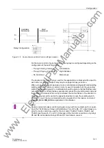
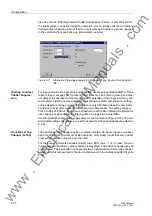
Figure 5-26
Error Message Resulting from Double Configuration
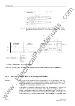
If a double point indication (DP) is configured to one binary input (e.g., feedback indi-
cations from switching devices), the next binary input is also set. If this configuration
is undone, the second binary input is automatically deconfigured.
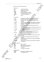
If a transformer tap changer indication is configured to a binary input, the next binary
inputs in order are also configured. Their total number is the same as the number of
bits configured for the transformer tap changer. If one of these inputs is deconfigured,
all related binary inputs are automatically deconfigured.
Configuring a
Function Key as a
Source
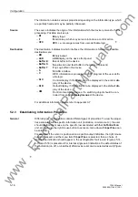
The four function keys on the front of the relay may also be configured as sources in
order to establish a link using CFC. In this situation, each function key may be linked
with
only one
internal indication. A function key may be occupied because it has al-
ready been set as an operating function for the relay. As delivered from the factory ,
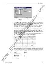
the device’s function keys F1, F2, and F3 are preconfigured:
In order to configure a new indication, select one of the options (OPEN/CLOSE, ON/
OFF, etc.) from the indication group in the information catalog and drag it to the left
Note
:
A single logical indication should not be configured to two binary inputs, since an OR-
link of both signals is not ensured. The operating program allows only
one
link, and
deletes the first link when a second is established. Use CFC to perform an “
25
” in-
stead.(
F1
operating messages
F2
primary measured values
F3
overview of the last eight fault messages
Note:
When an indication is configured to a function key, its factory-assigned function is de-
leted. Reestablishment of the factory default function of the F-keys is only possible by
initializing the relay with a new factory parameter set created within DIGSI
®
4. All de-
vice settings have to be reentered.
www
. ElectricalPartManuals
. com
Содержание siprotec 7SJ63
Страница 16: ...xiv 7SJ63 Instruction Manual C53000 G1140 C120 1 w w w E l e c t r i c a l P a r t M a n u a l s c o m ...
Страница 28: ...Introduction 1 12 7SJ63 Manual C53000 G1140 C120 1 w w w E l e c t r i c a l P a r t M a n u a l s c o m ...
Страница 112: ...SIPROTEC 4 Devices 4 38 7SJ63 Manual C53000 G1140 C120 1 w w w E l e c t r i c a l P a r t M a n u a l s c o m ...
Страница 346: ...Functions 6 182 7SJ63 Manual C53000 G1140 C120 1 w w w E l e c t r i c a l P a r t M a n u a l s c o m ...
Страница 494: ...Technical Data 10 48 7SJ63 Manual C53000 G1140 C120 1 w w w E l e c t r i c a l P a r t M a n u a l s c o m ...
Страница 604: ...Index Index 6 7SJ63 Instruction Manual C53000 G1140 C120 1 w w w E l e c t r i c a l P a r t M a n u a l s c o m ...


