Functions
6-120
7SJ63 Manual
C53000-G1140-C120-1
6.12
Frequency Protection (81 O/U)
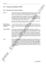
6.12.1 Description of Frequency Protection
General
The frequency protection function detects abnormally high and low frequencies in the
system. If the frequency lies outside the allowable range, appropriate actions are ini-
tiated, such as load shedding or separating a generator from the system.
A decrease in system frequency occurs when the system experiences an increase in
the real power demand, or when a malfunction occurs with a generator governor or
automatic generation control (AGC) system. An increase in system frequency occurs
when large blocks of load are removed from the system, or again when a malfunction
occurs with a generator governor or AGC system.
Through the use of filters and repeated measurements, the frequency evaluation is
free from harmonic influences and very accurate.
Underfrequency
and Overfrequency
Protection
Frequency protection consists of four frequency elements. Any given frequency ele-
ment can be set to pickup for either overfrequency or underfrequency conditions. Each
element can be independently set, and utilized to perform different functions within the
system.
Operating Ranges
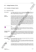
The frequency can be determined as long as the positive sequence voltages are
present and of sufficient magnitude. If the measurement voltage drops below a setta-
ble value
9PLQ
, then frequency protection is blocked. For elements used in an under-
frequency protection mode, as soon as the frequency of the measured voltage de-
creases below the setting, the element picks up and remain picked up until the system
frequency increases above the setting. For elements used in an overfrequency pro-
tection mode, as soon as the frequency of the measured voltage increases above the
setting, the element picks up and remains picked up until the frequency decreases be-
low the setting.
Logic
Each frequency element has an associated settable time delay. When a frequency el-
ement picks up and the time delay elapses, a trip signal is generated. When a frequen-
cy elements drops out, the control signal (tripping or alarm signal) is immediately ter-
minated, but not before the minimum command duration
70LQ75,3&0'
has
elapsed. Each of the four frequency elements can be blocked individually by binary
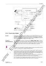
inputs. Figure 6-52 shows the logic diagram for the frequency protection function. The
81 element is a definite time element in that the time delay is not a function of the fre-
quency magnitude.
www
. ElectricalPartManuals
. com
Содержание siprotec 7SJ63
Страница 16: ...xiv 7SJ63 Instruction Manual C53000 G1140 C120 1 w w w E l e c t r i c a l P a r t M a n u a l s c o m ...
Страница 28: ...Introduction 1 12 7SJ63 Manual C53000 G1140 C120 1 w w w E l e c t r i c a l P a r t M a n u a l s c o m ...
Страница 112: ...SIPROTEC 4 Devices 4 38 7SJ63 Manual C53000 G1140 C120 1 w w w E l e c t r i c a l P a r t M a n u a l s c o m ...
Страница 346: ...Functions 6 182 7SJ63 Manual C53000 G1140 C120 1 w w w E l e c t r i c a l P a r t M a n u a l s c o m ...
Страница 494: ...Technical Data 10 48 7SJ63 Manual C53000 G1140 C120 1 w w w E l e c t r i c a l P a r t M a n u a l s c o m ...
Страница 604: ...Index Index 6 7SJ63 Instruction Manual C53000 G1140 C120 1 w w w E l e c t r i c a l P a r t M a n u a l s c o m ...


