Appendix
A-35
7SJ63 Manual
C53000-G1140-C120-1
A.3.3
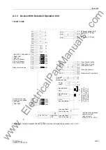
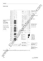
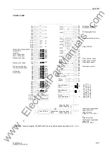
Devices With Detached Operation Unit
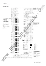
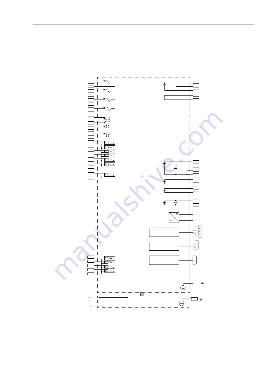
7SJ631
∗
–
∗
A/C
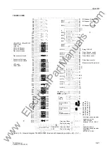
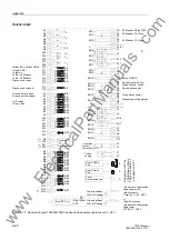
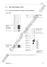
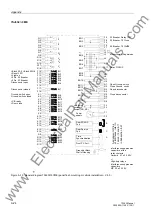
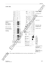
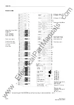
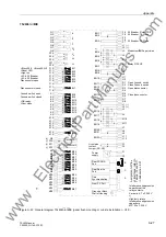
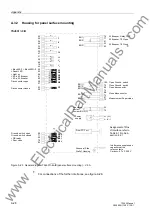
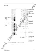
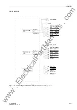
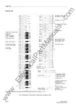
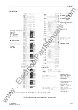
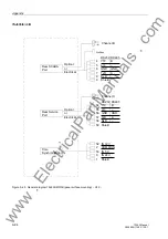
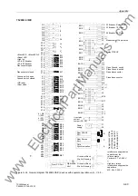
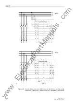
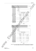
Figure A-30 General diagram 7SJ631
∗
–
∗
A/C (devices with separate operation unit) – V4.0 –
Power
Rear SCADA
Port
Time
Rear Service
Port
B
C
A
Ground at Back
supply
Wall of Housing
F1
F2
( )
~
+
-
Synchronization
Interference suppression
capacitors at the
Ceramic, 4.7 nF, 250 V
relay contacts,
Front PC Port
Operation
unit
Ground at Back
Wall of Housing
Q1
Q2
I
A
Q7
Q8
3I
0
Q3
Q4
I
B
Q5
Q6
I
C
R17
R18
V
c
R14
R16
V
a
R15
F17
F18
BI7
V
b
F10
F11
BI1
F13
F15
F16
F14
F12
BI2
BI4
BI5
BI6
BI3
R9
R10
R12
R13
R11
BI21
BI22
BI24
BI23
F9
F7
BO3
F6
F8
BO1
F5
BO2
R1
R2
BO11
R3
BO12
R4
BO13
R5
R6
R7
R8
BO14
BO15
Live status
F3
F4
contact
Jumper (NO, NC)
>Block 50-2, >Block 50N-2
>Reset LED
>Light on
>52-b, 52 Breaker
>52-a, 52 Breaker
Disconnector open
Disconnector closed
52 Breaker, Relay TRIP
52 Breaker, 79 Close
Open Ground. switch
Close Ground. switch
Open disconnector
Close disconnector
Measurement Supervision
52 Breaker, 79 Close
Ground. switch open
Ground. switch closed
>CB ready
>Door close
As
sig
n
m
ent
of
Pins
of Inte
rfac
es
,
re
fer to
Ta
ble
an
d 8
in
Sub
s
e
c
ti
on
www
. ElectricalPartManuals
. com
Содержание siprotec 7SJ63
Страница 16: ...xiv 7SJ63 Instruction Manual C53000 G1140 C120 1 w w w E l e c t r i c a l P a r t M a n u a l s c o m ...
Страница 28: ...Introduction 1 12 7SJ63 Manual C53000 G1140 C120 1 w w w E l e c t r i c a l P a r t M a n u a l s c o m ...
Страница 112: ...SIPROTEC 4 Devices 4 38 7SJ63 Manual C53000 G1140 C120 1 w w w E l e c t r i c a l P a r t M a n u a l s c o m ...
Страница 346: ...Functions 6 182 7SJ63 Manual C53000 G1140 C120 1 w w w E l e c t r i c a l P a r t M a n u a l s c o m ...
Страница 494: ...Technical Data 10 48 7SJ63 Manual C53000 G1140 C120 1 w w w E l e c t r i c a l P a r t M a n u a l s c o m ...
Страница 604: ...Index Index 6 7SJ63 Instruction Manual C53000 G1140 C120 1 w w w E l e c t r i c a l P a r t M a n u a l s c o m ...

