Installation and Commissioning
8-10
7SJ63 Manual
C53000-G1140-C120-1
o
The following equipment is needed:
- Grounded mat for protecting components subject to damage from electro-
static discharges (ESD).
- Screwdriver with a 6 mm wide tip,
- #1 Phillips screwdriver,
- 4.5 mm socket or nut driver,
o
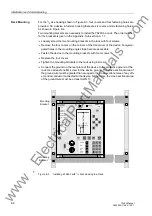
Unfasten the screw-posts of the D-subminiature connector on the back panel at loca-
tion “A”. This activity does not apply if the device is for surface mounting.
o
If the device has more communication interfaces at locations “B” and/or “C” on the
rear, the screws located diagonally to the interfaces must be removed. This activity is
not necessary if the device is for surface-mounting.
o
Remove the four corner caps on the front cover and loosen the screws that become
accessible.
o
Carefully pull off the front cover. The front cover is connected to the CPU board with
a short ribbon-cable.
For a device with a detached operator panel, the front part can be directly removed
after the screws are loosened.
o
At one end, disconnect the ribbon-cable between the front cover and the CPU board
(
å
). To disconnect the cable, push up the top latch of the plug connector and push
down the bottom latch of the plug connector. Carefully set aside the front cover.
For a device with a detached operator panel, this step is different. The 7-pin plug X16
must be removed from the CPU (
å
) board behind the D-subminiature plug and the flat
ribbon connector, which is connected to the 68-pin connector on the device side.
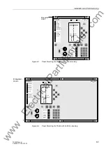
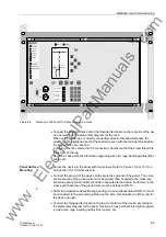
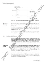
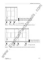
The locations of the printed circuit boards are shown in Figures 8-6 and 8-7.
o
Disconnect the ribbon-cables between the CPU board (
å
) and the I/O boards (
ê
).
o
Remove the boards and place them on the grounded mat to protect them from ESD
damage. A greater effort is required to withdraw the CPU board, especially in versions
of the device for surface-mounting, due to the communication connectors.
o
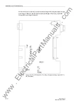
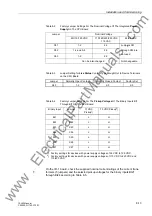
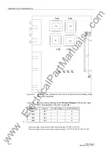
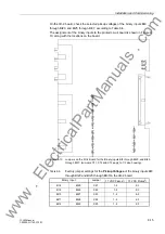
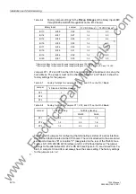
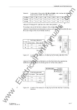
Check the jumpers according to Figures 8-8 to 8-12, and Tables 8-2 to 8-9. Change
or remove the jumpers as necessary.
Caution!
Electrostatic discharges through the connections of the components, wiring, plugs,
and jumpers must be avoided. Wearing a grounded wrist strap is preferred. Otherwise,
first touch a grounded metal part.
www
. ElectricalPartManuals
. com
Содержание siprotec 7SJ63
Страница 16: ...xiv 7SJ63 Instruction Manual C53000 G1140 C120 1 w w w E l e c t r i c a l P a r t M a n u a l s c o m ...
Страница 28: ...Introduction 1 12 7SJ63 Manual C53000 G1140 C120 1 w w w E l e c t r i c a l P a r t M a n u a l s c o m ...
Страница 112: ...SIPROTEC 4 Devices 4 38 7SJ63 Manual C53000 G1140 C120 1 w w w E l e c t r i c a l P a r t M a n u a l s c o m ...
Страница 346: ...Functions 6 182 7SJ63 Manual C53000 G1140 C120 1 w w w E l e c t r i c a l P a r t M a n u a l s c o m ...
Страница 494: ...Technical Data 10 48 7SJ63 Manual C53000 G1140 C120 1 w w w E l e c t r i c a l P a r t M a n u a l s c o m ...
Страница 604: ...Index Index 6 7SJ63 Instruction Manual C53000 G1140 C120 1 w w w E l e c t r i c a l P a r t M a n u a l s c o m ...

