Functions
6-9
7SJ63 Manual
C53000-G1140-C120-1
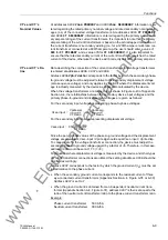
VT’s and CT’s
Nominal Values
At addresses
9QRP35,0$5<
and
9QRP6(&21'$5<
, information is en-
tered regarding the rated primary nominal voltage and rated secondary nominal volt-
ages (L-L) of the connected voltage transformers. At addresses
&735,0$5<
and
&76(&21'$5<
, information is entered regarding the primary and second-
ary ampere ratings of the current transformers. It is important to note that the primary
ampere rating of the current transformers is based on the actual tapped connection of
the current transformers’ secondary winding (i.e. for a 1200/5 ampere multi-ratio cur-
rent transformer connected at a 600/5 ampere tap, the user should enter a value of
600 for
&735,0$5<
and a value of 5 for
&76(&21'$5<
). It is also important to
ensure that the rated secondary current of the current transformer matches the rated
current of the device, otherwise the device will incorrectly calculate primary amperes.
VT’s and CT’s Ra-
tios
Data describing the connection of the current transformers and voltage transformers
is entered at addresses
,
and
.
Address
9SK9GHOWD
corresponds to the factor by which the secondary phase-
to-ground voltage must be adjusted relative to the secondary displacement voltage
(zero sequence voltage), and only applies in situations where the displacement volt-
age is actually measured by the device as opposed to calculated by the device.
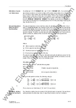
When the voltage transformers are connected as shown in Figure A-40 of Appendix
Section A.4, the relationships between the secondary device input voltages and the
primary phase-to-ground and displacement voltages are given as follows:
For the secondary input voltages representing phase-to-phase voltages:
For the secondary input voltage representing displacement voltage:
Since the per unit base values of the phase-to-ground voltage and the displacement
voltage are equivalent, Vsec-input / Vprim-
φ
g should equal Vsec-input / Vprim-disp.
To compensate for the voltage transformer connection, the device must adjust the
secondary phase-to-ground voltage upward by a factor of
√
3. Therefore, in this case,
address
would be set at 1.73 (=
√
3).
For situations where displacement voltage is measured by the device and other types
of voltage transformer connections are utilized, the setting at address
should be
modified accordingly.
Address
corresponds to the factor by which the ground current (I
N
) must be ad-
justed relative to the phase current.
•
When the secondary ground current corresponds to the residual current of three
wye-connected current transformers (Appendix Section A.4, Figure A-35 or A-39),
Address
is set to
.
•
When the ground current is obtained from an independent neutral current trans-
former (Appendix Section A.4, Figure A-37), address
is then set equal to the
ratio of the neutral current transformer ratio to the phase current transformer ratio.
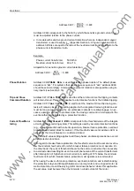
Example:
Phase current transformer
500 A/5 A
Neutral current transformer
300 A/5 A
Vsec-input
Vprim-
φφ
VT Ratio
------------------------
3
Vprim-
φ
g
VT Ratio
------------------------
⋅
=
=
Vsec-input
3
Vprim-disp
VT Ratio
----------------------------
×
=
www
. ElectricalPartManuals
. com
Содержание siprotec 7SJ63
Страница 16: ...xiv 7SJ63 Instruction Manual C53000 G1140 C120 1 w w w E l e c t r i c a l P a r t M a n u a l s c o m ...
Страница 28: ...Introduction 1 12 7SJ63 Manual C53000 G1140 C120 1 w w w E l e c t r i c a l P a r t M a n u a l s c o m ...
Страница 112: ...SIPROTEC 4 Devices 4 38 7SJ63 Manual C53000 G1140 C120 1 w w w E l e c t r i c a l P a r t M a n u a l s c o m ...
Страница 346: ...Functions 6 182 7SJ63 Manual C53000 G1140 C120 1 w w w E l e c t r i c a l P a r t M a n u a l s c o m ...
Страница 494: ...Technical Data 10 48 7SJ63 Manual C53000 G1140 C120 1 w w w E l e c t r i c a l P a r t M a n u a l s c o m ...
Страница 604: ...Index Index 6 7SJ63 Instruction Manual C53000 G1140 C120 1 w w w E l e c t r i c a l P a r t M a n u a l s c o m ...


