SIPROTEC
®
4 Devices
4-18
7SA522 Manual
C53000-G1176-C119-2
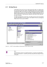
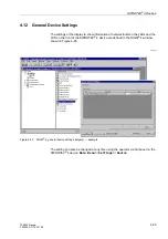
Figure 4-13
Screen of Device during Settings Transfer
Setting Sequence
When setting a SIPROTEC
®
4 device, adhere to the following sequence:
q
Specify the interfaces, the device data, and the time synchronization,
q
Determine the device functions to be used,
q
Design the assignment of the inputs and outputs using the configuration matrix,
q
Design all of the special logic that is to be employed using CFC (optional),
q
Enter the power system data,
q
Apply the settings to groups A to D (groups B to D optional),
q
Set the passwords.
Setting steps partially build on the decisions from the previous steps. By following the
sequence listed, unnecessary changes and rework are avoided. The sequence en-
sures that information required for an individual step will be available.
To design the control display, for example, the physical connections between the de-
vice and the primary equipment must be known. These connections are determined
and setup during configuration of the inputs and outputs in the matrix. During the dis-
play design, simply select the relevant available equipment indications, and assign
these indications with selected graphic symbols.
/2$'3$5$0(7(5
'RZQORDGDFWLYH
Note:
Changes to the configuration matrix and the control display are protected by password
No. 7 (Password for parameter set).
Содержание siprotec 7SA522
Страница 20: ...7SA522 Manual C53000 G1176 C119 2 ...
Страница 64: ...7SA522 Manual C53000 G1176 C119 2 ...
Страница 89: ...SIPROTEC 4 Devices 4 25 7SA522 Manual C53000 G1176 C119 2 Figure 4 20 CFC Logic example ...
Страница 408: ...7SA522 Manual C53000 G1176 C119 2 ...
Страница 456: ...7SA522 Manual C53000 G1176 C119 2 ...
Страница 516: ...7SA522 Manual C53000 G1176 C119 2 ...
Страница 620: ...Appendix B 48 ...

