Configuration
5-7
7SA522 Manual
C53000-G1176-C119-2
5.2
Configuration of the Binary Inputs and Outputs
General
Upon delivery, the display on the front panel of the relay, some of the function keys,
the binary inputs and outputs (output contacts) are assigned to certain information.
These assignments may be modified, for most information, allowing adaptation to the
local requirements.
During configuration, certain information within the relay is assigned to certain physi-
cal interfaces (e.g., binary inputs and output contacts) or logical interfaces (e.g., user-
defined logic, CFC).
It must be determined
which information
should be linked
with which
device
interface
.
It may also be determined which properties the information and the interfaces should
have.
Messages and statistical values from earlier events can be lost during configuration;
therefore, operational and fault data and statistic counters which are memorized in the
relay should be read and saved if desired, prior to changing the configuration.
5.2.1
Preparation
Before configuration is started, the overall interfacing requirements must be assessed.
The required inputs and outputs must be compared with the number of physical inputs
and outputs present on the relay. The types of indications and commands, and their
requirements, should be taken into account.
Indications
Indications may be information of the device regarding events and conditions that can
be transmitted via output contacts (e.g. start-up of the processor system or a trip signal
initiated by a protective function). These are defined as output indications.
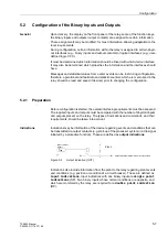
Figure 5-2
Output indication (OUT)
Indications also include information from the plant to the relay regarding plant events
and conditions (e.g. position or condition of a circuit breaker). These are defined as
LQSXWLQGLFDWLRQV
. Input indications with one binary input are
VLQJOHSRLQW
LQGLFDWLRQV
(SP). Two binary inputs whose normal conditions are opposite, and
which are monitored by the relay, are required for a
GRXEOHSRLQWLQGLFDWLRQ
(DP).
Trip
L+
(binary output
signal)
Output indication/tripcommand via relay contact
(Plant)
()
Содержание siprotec 7SA522
Страница 20: ...7SA522 Manual C53000 G1176 C119 2 ...
Страница 64: ...7SA522 Manual C53000 G1176 C119 2 ...
Страница 89: ...SIPROTEC 4 Devices 4 25 7SA522 Manual C53000 G1176 C119 2 Figure 4 20 CFC Logic example ...
Страница 408: ...7SA522 Manual C53000 G1176 C119 2 ...
Страница 456: ...7SA522 Manual C53000 G1176 C119 2 ...
Страница 516: ...7SA522 Manual C53000 G1176 C119 2 ...
Страница 620: ...Appendix B 48 ...

