Functions
6-10
7SA522 Manual
C53000-G1176-C119-2
Phase current transformers
500 A/5 A
Earth current transformer
60 A/1 A
•
Connection of the
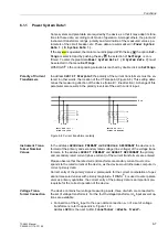
I
4
input to the earth current of the parallel line (for parallel line
compensation of the distance protection and/or fault location function, refer to Ap-
pendix A, Figure 1-11):
Address
is then set to:
=
,QSDUDOOLQH
and
usually address
is set to
=
1
.
If the set of current transformers on the parallel line however has a different ratio to
those on the protected line, this must be taken into account in address 0221:
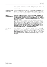
Address
is then set so that:
=
,QSDUDOOLQH
and
Address
so that
I
N paral. line
/
I
N prot. line
.
Example:
Current transformers on protected feeder1200 A
Current transformers on parallel feeder1500 A
•
Connection of the
I
4
input to the neutral current of a power transformer; this con-
nection can be used for the polarisation of the directional earth fault protection (refer
to Appendix A, Figure 1-12):
Address
is then set to:
=
,<VWDUSRLQW
, and
address
according to the ratio of the transformation ratios of the
current transformer in the transformer neutral and the set of current transformers on
the protected feeder.
•
If the
I
4
input is not required, the following settings are applied:
Address
=
1RWFRQQHFWHG
,
Address
is then irrelevant.
In this case the zero sequence current for the protection functions is computed by
means of the sum of the phase currents.
Rated Frequency
Address
5DWHG)UHTXHQF\
corresponds to the frequency at which the power
system operates. The preset value is dependent on the model number of the relay pur-
chased, and must be in accordance with the nominal frequency of the power system.
Phase Rotation
Address
is used to establish the phase rotation. The preset phase
sequence is “
L1 L2 L3
”. For systems that use a phase sequence of “
L1 L3 L2
”, address
must be set accordingly.
Units of Length
Address 0236 Distance Unit corresponds to the units of length (miles or km) applicable
to fault locating. Changing the length unit will not result in an automatic conversion.
The new setting values must be entered at the appropriate addresses.
Mode of Earth Im-
pedance (Residual)
Compensation
Matching of the earth to line impedance ratio is an essential prerequisite for the accu-
rate measurement of the fault distance (distance protection, fault location) during earth
faults. In address
the format for entering the residual compen-
sation is determined. It is possible to either use the ratio
5(5/
and
;(;/
or to enter
the complex earth (residual) impedance factor
.
. The actual setting of the earth (re-
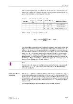
I
4
I
ph CT
⁄
60 1
⁄
500 5
⁄
-----------------
0.600
=
=
I
4
I
ph
⁄
1500
1200
-------------
1.250
=
=
Содержание siprotec 7SA522
Страница 20: ...7SA522 Manual C53000 G1176 C119 2 ...
Страница 64: ...7SA522 Manual C53000 G1176 C119 2 ...
Страница 89: ...SIPROTEC 4 Devices 4 25 7SA522 Manual C53000 G1176 C119 2 Figure 4 20 CFC Logic example ...
Страница 408: ...7SA522 Manual C53000 G1176 C119 2 ...
Страница 456: ...7SA522 Manual C53000 G1176 C119 2 ...
Страница 516: ...7SA522 Manual C53000 G1176 C119 2 ...
Страница 620: ...Appendix B 48 ...


