Configuration
8.
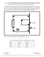
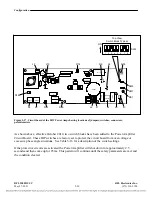
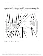
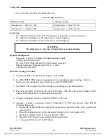
Connect a 50 Ohm non-inductive load (50W minimum rating) across TP1 “Input” and TP2
“Common”.
9.
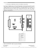
Remove either the Balance Board or the External Amp Connection Board depending on which
is present in the RF Chassis ).
10.
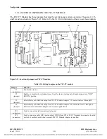
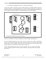
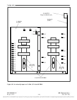
Adjust L1 (right coil) for a minimum level on the meter. The coil is adjusted by turning the
plastic nut accessible from the front of the module. If a null is not seen, the lowest value of the
first series capacitance may have to be varied, use the schematic as a guide.
11.
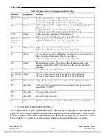
Set Jumper J44 in the “TEST” position.
12.
Adjust L2 (left coil)for a minimum level on the meter. The coil is adjusted by turning the
plastic nut accessible from the front of the module. If a null is not seen, the lowest value of the
second series capacitance may have to be varied, use the schematic as a guide.
13.
Set Jumper J44 back to the “normal” position.
14.
Tighten the screws to lock the air core coils L1 & L2 into position.
15.
Reattach the hood with the two screws that were removed earlier.
16.
Reinstall the Balance Board or the External Amp Connection Board that was removed earlier.
17.
Verify that all modules are seated securely.
18.
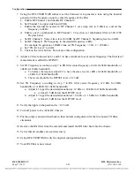
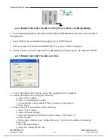
Using RFL 9508D NMS write the original configuration back.
19.
Your Tx Filter is now tuned.
RFL 9508D UCC
RFL Electronics Inc.
May 27, 2011
5-34
(973) 334-3100

