Configuration
5.3.1.8
SETTING JUMPERS ON TRANSCEIVER MODULE ADAPTER
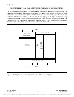
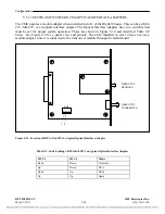
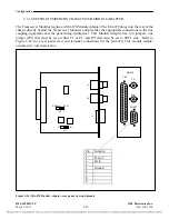
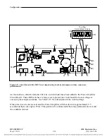
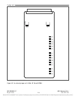
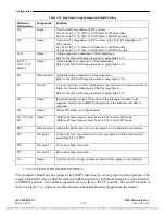
The Transceiver Modules require an MA-470 Module Adapter. The MA-470 plugs into the rear of the
chassis directly behind the Transceiver Modules and provides the appropriate connections to the line
coupling equipment and the packetizing multiplexer. This Module Adapter has two jumpers, one
jumper (JP1) that must be set to either T1 or E1; and JP3 that must be set to SPCL side. Refer to
Figure 5-14 for a rear panel view and terminal connections for the MA-470. This module adapter
occupies two rear chassis slot.
Pin Function
1 -
2 Tx
Out
3 Rx
In
4 -
5 Ground
6 -
7 -
8 -
9 -
MA-470
V.35
TX
RX
CRAFT
NORMAL SPCL
JP3
T1 E1
JP1
J5
J6
J1
Figure 5-15. MA-470 Module Adapter, rear panel view and pinouts
RFL 9508D UCC
RFL Electronics Inc.
May 27, 2011
5-26
(973) 334-3100

