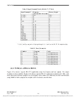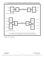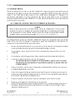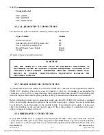
Installation
Connector
Label
EXT AMP IN
EXT
AMP
OUT
EXT AMP FAIL IN
3.5.6
3.5.7
3.5.8
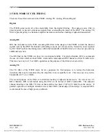
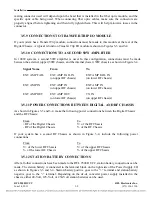
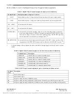
ALARM OUTPUT CONNECTIONS
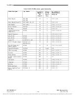
The user has the option to make the following Alarm output connections.
Type
of
Alarm Chassis
Internal
Amp
Fail
RF
External Amp Fail (100W systems only)
RF
Power Amp Power Supply Fail
RF
Digital
Chassis
Power
Supply
Digital
TT
Fail Digital
All alarm relays are normally energized.
WARNING
THE RFL 9508D UCC CHASSIS MUST BE PROPERLY GROUNDED AS
DESCRIBED IN THE FOLLOWING PARAGRAPH BEFORE ATTEMPTING TO
CONNECT INPUT POWER. IMPROPER GROUND CONNECTIONS MAY
RESULT IN SYSTEM MALFUNCTIONS, EQUIPMENT DAMAGE, OR
ELECTRICAL SHOCK.
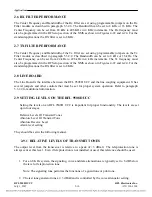
CHASSIS GROUND CONNECTIONS
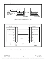
A ground stud at the lower right rear of the RFL 9508D UCC chassis is the main ground for the RFL
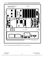
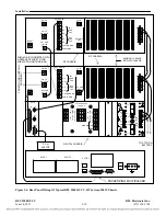
9508D UCC terminal. This can be seen in Figures 3-3 and 3-4. Grounding is accomplished by
connecting a wire 6AWG or larger between this ground stud and rack ground. The grounding wire
should be kept as short and straight as possible, to keep its resistance and inductance to a minimum.
Before attempting to make power connections, make sure the RFL 9508D UCC terminal is equipped
with a power supply designed to operate at the available input supply voltage. This can be determined
by checking the model designator on the module handle. If an external power supply is being used,
check the markings on the external power supply. If the wrong voltage is connected to the power
supply, component damage will result.
FIBER OPTIC CONNECTIONS
If your RFL 9508D UCC
is equipped with Fiber Optic Modules, fiber optic connectors must be
connected to the fiber optic heads on the rear panel of the 9508D
chassis. Type ST series bayonet fiber
optic connectors (or their equivalent) are used with both singlemode and multimode fibers. The exact
RFL 9508D UCC
RFL Electronics Inc.
June 14, 2011
3-8
(973) 334-3100

