


Configuration
5.2.6
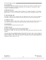
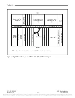
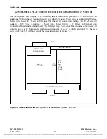
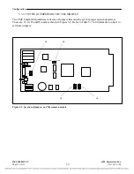
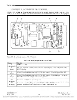
MODULE PLACEMENT IN THE 9508RT CHASSIS (WHEN
SUPPLIED)
1
2
3
4
5
7
6
8
13 14 15 16 17 18
9
10 11 12
NOTE 1: This cable must be installed when a second PLC-TT module Adapter is installed.
SEE NOTE 1.
FRONT
REAR
MAIN
POWER
SUPPLY
RE
DUN
DA
NT
PO
W
ER
SU
P
PL
Y
TEST PANEL
MOTHER BOARD
PL
C-
TT
MODU
L
E
CM
-4
M
A
IN
MA-2
7
1, MA-2
78
OR OP
T
ICA
L
I/
O
POWER
SUPPLY
ALARM I/O
4-FUNCTION PLC-TT
MODULE ADAPTER
"A"
4-FUNCTION PLC-TT
MODULE ADAPTER
"B"
Figure 5-7. Module placement for 9508RT
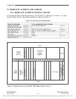
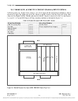
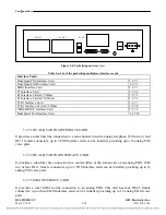
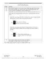
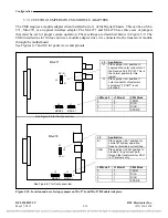
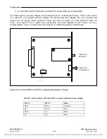
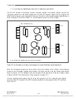
5.2.7
MODULE PLACEMENT IN THE PACKETIZING MULTIPLEXER
The packetizing multiplexer is a 2U high chassis which contains the different interfaces and channel
cards that can be required in a system.
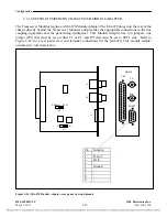
Figure 5-8 shows the rear view of the chassis; the unit has three
slots where cards are plugged in to provide for different interfaces of voice and data channels.
Table 5-6 list the different channel cards available to use on the packetizing multiplexer.
Any of the interface cards can be placed in any of the available slots, nevertheless, some interface
cards can not be placed in more than one any slot.
RFL 9508D UCC
RFL Electronics Inc.
May 27, 2011
5-13
(973) 334-3100


