Installation
3.5
CONNECTIONS
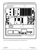
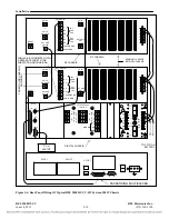
Electrical connections are made to each RFL 9508D UCC chassis through the terminal blocks and
connectors on the chassis rear panel. The rear panel of a typical RFL 9508D UCC terminal is shown in
Figure 3-3 for a 50W system, and in Figure 3-4 for a 100W system. Paragraphs 3.5.1 through 3.5.10
provide basic descriptions of all the connections that must be made. Refer to the “as supplied”
drawings furnished with your RFL 9508D UCC for more detailed descriptions of the connections that
must be made to your system.
3.5.1
MAKING CONNECTIONS TO TERMINAL BLOCKS
NOTE
Before making connections to terminal blocks, check the configuration of all rear panel
modules. It is easier to configure the rear panel modules prior to connecting field wiring.
The configuration of these modules usually requires the setting of programmable jumpers
and DIP switches as described in paragraphs 5.3.1.2, 5.3.1.3, 5.3.1.5, and 5.3.1.8.
The terminal blocks on the rear of the RFL 9508D UCC chassis are conventional screw-type barrier
blocks. Wires can either be stripped or terminated in spade lugs, depending on local practice. To
connect wires to the terminal blocks, proceed as follows:
1.
Remove the transparent protective cover from the rear of the chassis by loosening the mounting
screws and sliding the panel up and off of the standoffs holding it in place.
2.
Using strippers, remove about 1/4 inch (10 cm) of insulation from the end of the wire to be
connected.
3.
If local practice calls for lugged wires, crimp a spade lug onto the stripped end of the wire.
4.
Locate the terminal to which the wire is to be connected.
All terminals blocks are numbered. Terminal numbers appear on the rear panel,
directly below the terminal block. Terminal block numbers are directly below the
terminal numbers.
5.
Using a screwdriver, turn the screw at that position counterclockwise until the wire or lug can
be slipped underneath the screw head.
6.
If the wire is lugged, slip the lug under the screw head. If lugs are not being used, use a pair of
needle-nose pliers to bend the stripped end of the wire into a hook, and slip this hook under the
screw head so that the hook surrounds the screw.
7.
Using a screwdriver, turn the screw clockwise until tight to secure the wire in place.
8.
Repeat steps 2 through 8 for all other wires to be connected.
9.
Line up the mounting holes in the rear panel protective cover with the standoffs on the rear of
the chassis, and push in and down on the protective cover until it is secured in place. Then
tighten the mounting screws.
RFL 9508D UCC
RFL Electronics Inc.
June 14, 2011
3-6
(973) 334-3100

