


RFL Network Management Software
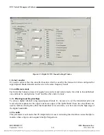
5. F6 Time Slot
This box contains the time slot number used to communicate the teleprotection information inside the
digital chassis.
6. Data Attenuation
This pull down box is used to select the attenuation of the QAM spectrum, in a default application this
attenuation should be set to 6 dB.
7. Pilot Attenuation
This pull down box is used to select the pilot level attenuation. When the analog transceiver is
transmitting the pilot tone, this value is set to the maximum attenuation of 256 dB.
8. Bandwidth
This pull down box let the user select among 2 KHz, 4 KHz or 8 KHz operating ranges. The maximum
bit rate, at which the equipment will communicate, depends on this bandwidth selection.
For a 62.4 KHz bit rate operation, 8 KHz bandwidth must be selected.
9. Tx Frequency
This pull down box is used to specify the transmit band’s lower edge frequency.
For example, if the transmit stream occupies form either 200 to 204 KHz or 200 to 208 KHz; this
parameter is set to 200 KHz.
10. Rx Frequency
Through this pull down box you can select the receive band’s lower edge frequency
For example, if the receive stream occupies from either 104 to 108 KHz or 104 to 112 KHz, the Rx
Frequency is set to 104 KHz.
11. AGC Setpoint
This parameter indicates a reference point for the Automatic Gain Control to work properly, for the
default application, the AGC setpoint should be set to 20.
12. Bit Rate Settings
Using this group of check boxes, the user can select the desired bit rates at which the 9508D will
connect, according to the transmission line quality conditions (attenuation, noise level, etc); the link
will be established at the most suitable bit rate among the group of options selected.
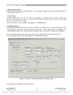
13. Status
This is a group of status parameters indicated as checked checkboxes when active. They indicate the
status of the negotiation between both end equipment. Once the link has been established, ‘connection’
is the only status that is active.
14. TX/RX Connected Bit rate
This status boxes will show the current TX and RX bit rates once the link is established and a read
operation have been performed.
15. Round Trip
This is a status value which indicates the delay in milliseconds of the data from the local to the remote
equipment and back. This parameter is available after a read operation has been performed.
RFL 9508D UCC
RFL Electronics Inc.
September 7, 2012
4-16
(973) 334-3100


