


RFL VF-5XP
RFL Electronics Inc.
July 10, 2007
23
(973) 334-3100
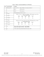
12. Chan 1 Loopback
In normal operation, all loopbacks are disabled. Loopback settings are used for troubleshooting
purposes. There are three loopback settings as follows: None (disable all loopbacks), Local (enable
local loopback), Remote (enable remote loopback).
13. Chan 2 ON/OFF
Channel 2 can be set to ON or OFF.
When set to ON, Channel 2 is enabled (ON).
When set to OFF, Channel 2 is disabled (OFF).
14. Tx2 Level Adjust Sign
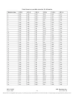
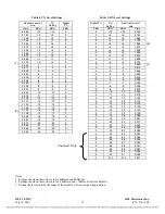
The Tx2 Level can be set from –23dBm to +10dBm in 0.5dBm steps. First select the sign by clicking
on the (+ or -), then select the level as described in step 15 below.
15. Tx2 Level Volume (db)
The Tx2 Level can be set from –23dBm to +10dBm in 0.5dBm steps. Select the level by clicking on
the level you want, in the pull down box.
16. Rx2 Level Adjust Sign
The Rx2 Level can be set from –31.5dBm to +10dBm in 0.5dBm steps. First select the sign by
clicking on the (+ or -), then select the level as described in step 17 below.
17. Rx2 Level Volume (db)
The Rx2 Level can be set from –31.5dBm to +10dBm in 0.5dBm steps. Select the level by clicking on
the level you want, in the pull down box.
18. Chan 2 Signaling
When set to enabled, Chan 2 Signaling is active (in use).
When set to disabled, Chan 2 Signaling is inactive (not in use).
19. Chan 2 Busy/Not Busy
The Chan 2 Busy/Not Busy parameter allows the user to activate or deactivate the Busy function by
selecting Busy, or Not Busy.
20. Chan 2 2kHz Test Tone
The Chan 2 2kHz Test Tone and be turned On by selecting Enable, or turned Off by selecting Disable.
21. Chan 2 Loopback
In normal operation, all loopbacks are disabled. Loopback settings are used for troubleshooting
purposes. There are three loopback settings as follows: None (disable all loopbacks), Local (enable
local loopback), Remote (enable remote loopback).
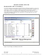
After all VF-5XP parameter selections have been made they must be written to the VF-5XP card in the
network. This is done by using the “WRITE” operation as described in Section 4 of the RFL 9508
Instruction Manual.


