


INSTALLATION
Before the RFL VF-5XP can be placed in service, it must be installed in an RFL 9508 digital chassis.
Installation involves determining the module slot in the digital chassis where the module will be
installed, inserting a Module Adapter into the rear of the shelf behind the module slot, connecting all
signal wiring to the Module Adapter, checking the module address settings and jumpers, inserting the
module into the front of the chassis, and using UCC 2020 NMS software to configure the module.
NOTE
Power supply and time slot considerations may affect the installation of this module
into an existing multiplexer shelf. Refer to the multiplexer manual for more information.
The following instructions are provided for installing RFL VF-5XP modules into existing systems. If
the module was included as part of a system, installation was done at the factory. Otherwise, proceed
as follows:
1.
Carefully inspect the module for any visible signs of shipping damage. If you suspect damage
to the module, immediately call RFL Customer Service at the number listed at the bottom of
this
page.
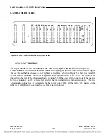
2.
Determine the module slot in the RFL 9508 or multiplexer chassis where the module will be
installed.
The RFL VF-5XP module occupies one module slot in the RFL 9508 or
multiplexer chassis, however, in some cases the next highest front module slot must
be left blank since some module adapters occupy two rear slots.
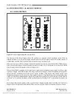
3.
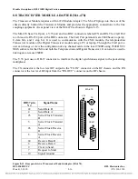
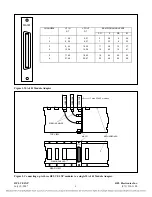
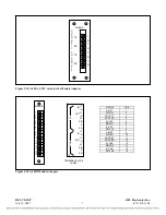
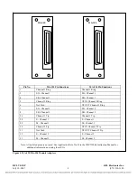
Determine which Module Adapter will be used to make connections to the RFL VF-5XP
module.
The VF-5XP requires a Module Adapter. The module adapter provides the
appropriate connectors for the desired interface. There are five Module Adapters
compatible with the RFL VF-5XP:
RFL VF-5XP
RFL Electronics Inc.
July 10, 2007
4
(973) 334-3100


