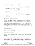
When input becomes inactive, it immediately sends a code to deactivate output (code-1). This causes
the output to become inactive immediately.
The priority logic is such that the activation of any arrangement of inputs will cause the proper outputs
to be activated although only function 1 will be extended. When function 1 input is deactivated
however, all outputs will be deactivated.
REMOTE CONTROL USING NMS
PROGRAMMING THE PLC-TT MODULE
The PLC-TT module must be programmed using NMS (Network Management Software) version 10.5
or later. Refer to the IMUX 2000 Instruction Manual for information on using NMS. To program the
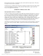
PLC-TT module go to the PLC-TT View or Change a Card Window, as shown in Figure 7. This is
where a user can view or change PLC-TT settings. The “Actual” column is what the PLC-TT is
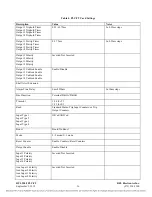
actually set to, and the “Set to” column contains settings the user can change. Refer to Table 4 for a list
of PLC-TT card settings, and Table 5 for a card status listing. When finished with either viewing or
changing the PLC-TT settings, click on Exit to return to the Display/Change Node window.
After all PLC-TT parameter selections have been made they must be written to the PLC-TT card in the
network. This is done by using the “WRITE” operation as described in the IMUX 2000 Instruction
Manual.
Figure 7. View or Change a Card Window for the PLC-TT module
RFL 9508 PLC-TT
RFL Electronics Inc.
September 5, 2012
15
(973) 334-3100

