


Commissioning Procedure
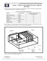
Section 6.
6.2.1
COMMISSIONING PROCEDURE
6.1
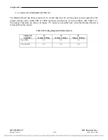
REQUIRED EQUIPMENT
o
9508D Manual/CD (as required).
o
PC with 9508D NMS Installation Disk (as required).
o
Copy of the NMS Parameters File (supplied with system CD).
o
RS232 strait-through Cable 9-Pin Female to Female
o
FSVM-Frequency Selective Voltmeter & Cabling for test set
o
50 or 100-Watt Dummy Load
o
RF Board Extender Card (Part No.107885)
o
Hex adjustment tool
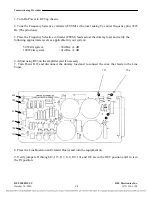
WARNING!
THE 9508D CARRIER OUTPUT CONNECTOR MUST BE TERMINATED PROPERLY
BEFORE BEING ENERGIZED. FAILURE TO DO THIS MAY RESULT IN DAMAGE TO
THE TX FILTER. SEE STEP 4. BELOW.
CAUTION
THE POWER AMPLIFER WILL SHUTDOWN IF NOT PROPERLY TERMINATED
CONDUCT LINE TUNING PROCEDURES AT REDUCED POWER LEVELS.
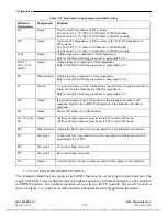
(FSK – Guard, ON/OFF – Reserve Key)
6.2
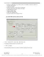
COMMISSIONING PROCEDURE
AF CHASSIS INITIAL POWER UP
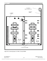
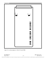
1. Before turning power on, verify proper Input Voltage and voltage polarity connections.
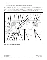
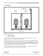
2. Verify proper Ground connections for all the chassis AF, RF and packetizing multiplexer chassis
utilizing GND studs on Power Supply IO.
3. Remove coax from chassis to line tuner.
4.
Connect 50 Ohm non inductive dummy load of sufficient wattage to the carrier output
connector (4W Tx or 2 W I/O). Reference Paragraph 6.2.5.1
5. Seat all modules firmly in the chassis.
6. Turn on the TOP AF Power Supply Switch only.
RFL 9508D UCC
RFL Electronics Inc.
October 14, 2010
6-1
(973) 334-3100


