RFL VF-5XP
RFL Electronics Inc.
July 10, 2007
9
(973) 334-3100
4.
Insert the desired Module Adapter into the rear of the slot which will hold
the RFL VF-5XP
module and make all connections to the Module Adapter.
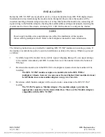
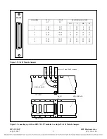
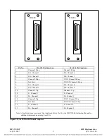
If an MA-301, MA-322 or MA-324 Module Adapter is being used, plug the 50-pin
Telco connector into its 50-pin connector.
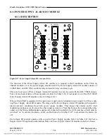
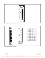
If an MA-301A Module Adapter is being used, connect all signal wiring to the
terminal strip at the rear of the MA-301A using Figure 3 as a guide.
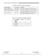
If an MA-301B Module Adapter is being used, connect all signal wiring to the
terminal strip at the rear of the MA-301B using Figure 4 as a guide.
5.
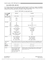
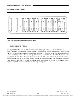
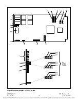
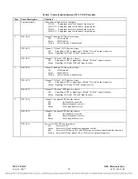
Refer to Figure 6 and Table 1 for the location of switches, controls and indicators on the VF-
5XP.
6.
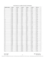
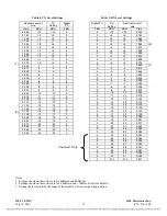
Set DIP switches SW1-1 through SW1-6 for the desired remote access address.
For remote access, each channel module in the RFL 9508 or IMUX 2000 must have
a distinct module address. Valid module addresses are the numbers 1 to 36. In
most installations, the address will be set to the slot number of the shelf the module
is occupying. Table 2 shows the switch settings for the module address.
7.
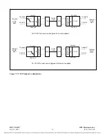
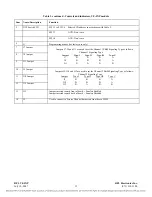
Set jumpers J7, J8 and J11 to select the type of E&M signaling required for Channel 1. Set
jumpers J9, J10 and J12 to select the type of E&M signaling required for Channel 2.
There are four signaling types: Type I, Type II, Type III and Type V. Refer to
Table 1 on page 18? for jumper assignments for each of these signaling types.
8.
The RFL VF-5XP is now installed. You can now change the operating parameters of the
module by using NMS as described on page 21 of this document. For more information on
NMS, consult the RFL 9508 Instruction Manual.

