Applications
RFL 9508D UCC
RFL Electronics Inc.
2.1.2
TANDEM LINK WITH INCORPORATED BRANCH EXCHANGE
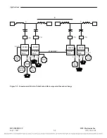
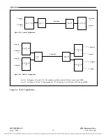
Figure 2-2 illustrates two point-to-point applications connected together by an Ethernet link.
The link between nodes A and B one SCADA channel, integrated F6 teleprotection and a speech
channel that communicates a PABX at node A which can be used to call subscriber at node B and also
the subscriber at node C by using the incorporated features of Automatic Branch Exchange of the
packetizing multiplexer.
The two 9508Ds at node B are connected together by Ethernet port, traditionally the two links were
connected together at the audio level, which increased group delay distortion. This severely limited the
number of links that could be connected together in tandem.
The FXO port at node A can be configured to ‘Auto-Dial’ the suscriber extension at node B or C, or
can be used to access the multiplexer’s branch exchange by using section dialing: First the PABX’s
FXO port extension number must be dialed to access the multiplexer’s 2W port, then, the dial rules to
follow are those configured in the multiplexer.
The 2W FXS port at node B can be used to call to node C or to access the PABX at node A. Also an
Auto Ring Down voice channel is provided between nodes B and C (ARD), this can be configured as a
point-to-point voice channel or as a autodial extension, so, other extensions (Node A for example) can
dial to this locations.
Each 9508D terminal is connected to the power line via an LTU (Line Tuning Unit) and coupling
capacitor (CC). The LTU matches the characteristic (surge) impedance of the power line to the
impedance of the 9508 terminal. The LTU also contains a surge arrestor to protect the equipment from
voltage spikes, lightning or other faults. The coupling capacitor isolates the 9508 from the high voltage
of the power line.
A 21P device is shown at nodes A and B. The 21 indicates that the device is a distance (under
impedance) relay. The P indicates that there is a pilot channel communication link. In this example the
RFL 9508D equipment provides the pilot channel. The A-B indicates that the communication channel
is from node A to node B. Conversely, the B-A indicates that the communication channel is from node
B to node A.
A 21P device is also shown at nodes B and C. The B-C indicates that the communication channel is
from node B to node C. Conversely, the C-B indicates that the communication channel is from node C
to node B.
When the 21P distance relay at node A detects a fault in the forward direction, it provides a contact
closure to the PLC-TT module at the local end (node A). The PLC-TT module sends the contact
closure information to the remote end (node B) PLC-TT module over RF Channel 2 of the 9508D
power line carrier link. The PLC-TT module can support up to four bi-directional transfer trip
functions between two terminals, or can support DCB (Directional Comparison Blocking) in addition
to two transfer trip functions. Teleprotection between nodes B and C is provided in a similar manner.
July 1, 2007
2-3
(973) 334.3100

