RFL 9508
RFL Electronics Inc.
June 2005
5
UCC Physical Characteristics
Dimensions: 3.5" H x 16.8 “ W x 12.2” D
(8.9 cm H x 42.7 cm W x 31 cm D)
Typical weight: 10 lbs. (4.5 kg)
Environmental Tolerances
•
Operating Temperature: 0° to 45° Celsius
•
Relative Humidity: 10% to 90%, non – condensing
Tested Under the Following
Standards
IEC 60834-1, IEC 60068-1-1, IEC 60068-2-2, IEC 60068-2-3,
IEC 60255-1, IEC 60255-21-2, IEC 60255-21-3
Integrated or External
Teleprotection
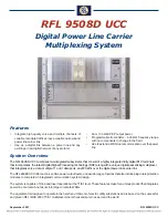
The RFL 9508D UCC is available with either integrated
teleprotection or with an external distant teleprotection sys-
tem known as RFL 9508 RT. Both systems use a four func-
tion plug-in Modular Transfer Trip System (MTS) based on
the proven F6 protection scheme.
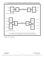
The system is suitable for Direct Transfer Trip (DTT), Permis-
sive Transfer Trip (PTT), Blocking and Unblocking applica-
tions. The RFL 9508D UCC and RFL 9508 RT comply to the
IEC-60834 teleprotection standard.
The MTS system is comprised of two parts, the MTS module
and the I/O modules. Together these modules work with the
balance of the RFL 9508D UCC system to provide four-func-
tion teleprotection. Up to two MTS modules can be used in
each system to provide up to eight functions of teleprotection.
The MTS module senses the inputs, de-bounces them, ap-
plies a small amount of logic, and passes them in a timeslot
on the E1/T1 link to the transceiver. The MTS limits com-
mands to 2 seconds, returning to the guard states after that
time, even if the inputs remain keyed. The MTS user interface
is in the IMUX NMS. Two and four function relay and solid-
state I/O’s are available. Additional I/O for providing parallel
contacts is also supported.
The PLC transceiver DSP decodes the message from the MTS
and creates the necessary tones to transfer the command to
the other end. The other end receives the tones, performs the
necessary actions to generate the needed security and depend-
ability, and sends the information to the MTS via the E1/T1 link.
RFL 9508D UCC
•
FTP upload and download of software and configura-
tion
•
Username/password security control, Radius Authen-
tication for console and Telnet access
•
Administrative filtering
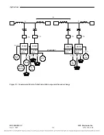
RFL 9508 RT Distant Teleprotection via Optic Link
Many times the protective relays are not located in the same
building as the communications systems that are used to
transmit the relaying signals. A unique feature of the RFL
9508D UCC is that the teleprotection modules can be housed
in a separate chassis and communicate with the RFL 9508D
UCC via fiber optic cable The teleprotection chassis can be
located up to 113km (70 miles) from the RFL 9508D UCC
depending on the type of fiber optic transceiver selected. This
chassis is known as the RFL 9508 RT.
General Specification
F6 teleprotection is a single tone system that sends only one
tone at a time, making it ideal for PLC. Different combina-
tions of inputs use a priority scheme to generate the correct
tone and the correct output on the receiving side. This sys-
tem can have two, four or eight inputs and outputs, which are
programmable. Each input can be optionally inverted or not
and if 8 inputs are employed, paired inputs can be AND’ed or
OR’ed to form each of the 4 command inputs.
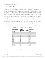
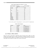
Once the input commands have been determined, the trans-
mitted command is determined according to the priority chart.
Two charts are available, based on the mode setting, “2+2”
or “3+1” each provides up to four prioritized commands. The
2+2 mode is typically used for parallel line applications, while
the 3+1 mode is typically used for single pole trip applica-
tions. The transmitted command is sent to the PLC trans-
ceiver after an appropriate de-bounce period.
Integrated Test Switch
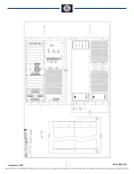
The MTS module supports the connection of an internal test
panel. The test panel can be mounted inside the door of the
chassis and connect to the MTS via an 8 wire cable.
The test panel has a 10 position rotary switch, a push-button,
and two-toggle switches. The rotary switch has Normal, In-
put #1, Input #2, Input #3, and Input #4 positions. The test
switch can accommodate 2 MTS cards.
Selecting input 1 through 4 positions will not do anything until
the push-button is pressed. Pressing the push-button will send
the command corresponding to the selected position.
The toggle switch disables the local outputs.
Depending on the mode and the command, the transceiver sends
one frequency for the entire time or switches back and forth
between two frequencies. The single frequency is considered
un-coded operation. Un-coded is less secure and is used for
permissive or blocking applications. Coded transmission con-
sists of two frequencies sent one after the other for a specified
time. The receiver must receive each tone for a specified time
period before declaring a valid trip reception.
September 2007

