Configuration
5.3.2.2.1
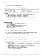
TX FILTER TUNING PROCEDURE
Required Equipment:
•
Frequency Selective Voltmeter with high impedance input
•
50 Ohm non-inductive load (50 Watt minimum rating)
•
PC with 9508D NMS, and RS-232 9-pin female connection.
•
11/32” hexagonal nut driver
•
Philips head screwdriver
Tx Filter Tuning Procedure:
1.
Use RFL 9508D NMS software to generate a list of appropriate jumper settings. Refer to
section 4 of the manual for more information on RFL 9508D NMS.
2.
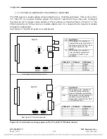
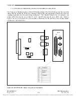
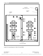
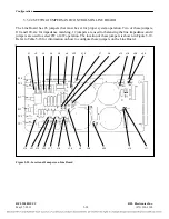
Remove the Tx Filter from the chassis and open the hood, by removing the two screws on the
top. Also loosen the two screws that lock the air core coils L1 and L2 in place.
3.
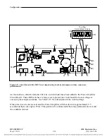
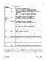
Set the Tx Filter jumpers for center frequency according to your configuration. If needed, spare
jumpers are shipped with each unit.
4.
Set the 8kHz/16kHz bandwidth jumper to the appropriate position.
5.
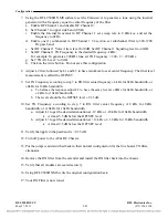
Using the RFL 9508D NMS software set the Transceiver to generate a tone using the internal
generator with a frequency equal to center frequency of the filter.
a.
Enable RF Channel 1 and disable RF Channel 2.
b.
Set Channel 1 to upper side band (USB).
c.
Enable the Internal Generator in RF Channel 1, set sweep rate to 0 kHz/sec, and set the
frequency to 2kHz.
d.
Enable one (1) subchannel in RF Channel 1 Tx section, set subchannel filter to 300-3700
Hz pass band.
e.
Set RF Channel 1 Voice Atten. level for 0dB, Set RF Channel 1 Signaling level to -42dB.
f.
Set RF Channel 1 TX Frequency to TX filter center frequency - 2 kHz
For example:
•
Tx Filter Center Frequency = 300 kHz
•
Set TX Frequency = 300 - 2 = 298 kHz
g.
Set “TX Att Level” to 0 dB.
h.
Click on the write button. Do not save this configuration.
6.
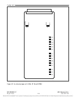
On the Tx Filter board, set Jumper J44 in the “NORM” position.
7.
Connect a Frequency Selective Voltmeter (FSVM) to TP1 “Input” and TP2 “Common”.
RFL 9508D UCC
RFL Electronics Inc.
May 27, 2011
5-33
(973) 334-3100

