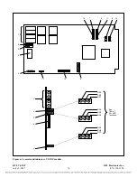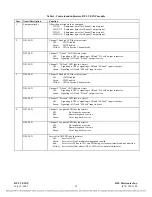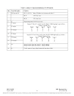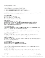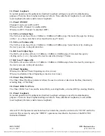
Table 1. continued - Controls and indicators, VF-5XP module
Item Name/Description
Function
5
DIP Switch SW1
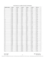
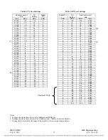
SW1-1 to SW1-6 Selects SCB address in accordance with Table 2.
SW1-7: AUX: Don’t care
SW1-8: AUX: Don’t care
6
J1
Programming header (for factory use only)
7 J7
Jumper
8 J8
Jumper
9 J11
Jumper
10 J9
Jumper
11 J10
Jumper
12 J12
Jumper
13 J13
Jumper inserted toward front of board = Sonalert Enabled
Jumper inserted toward back of board = Sonalert Disabled
14
J2
Used to connect to Service Channel harness on front door of 9508.
Jumpers J7, J8 and J11 are used to set the Channel 1 E&M Signaling Type as follows:
Channel 1 Signaling Type
Jumper Type I Type II Type III Type V
J7 B B B A
J8 B B B A
J11 B A B B
Jumpers J9, J10 and J12 are used to set the Channel 2 E&M Signaling Type as follows:
Channel 2 Signaling Type
Jumper Type I Type II Type III Type V
J9 B B B A
J10 B B B A
J12 B A B B
RFL VF-5XP
RFL Electronics Inc.
July 10, 2007
13
(973) 334-3100

