


Configuration
5.3.1.5
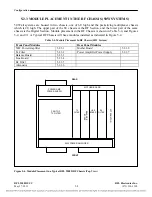
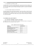
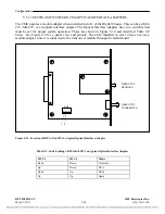
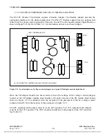
SETTING JUMPERS ON THE PLC-TT MODULE ADAPTER
The PLC-TT Transfer Trip Module requires a Module Adapter. The Module Adapter provides the
appropriate interface for the desired application. The PLC-TT Module Adapter has two jumpers that
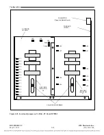
must be set for proper system operation. These are J4 and J5 on the module adapter Input Board, as
shown in Figure 5-12. Refer to Table 5-11 for information on how to set these jumpers.
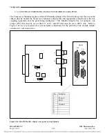
125V
48V
125V
48V
INPUT TERMINAL
BLOCK
J5
J4
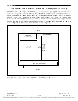
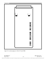
For 48V OPERATION, JUMPERS SHALL BE LOCATED AS SHOWN
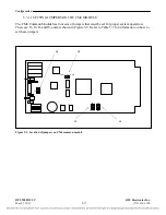
Figure 5-13. Location and use of voltage control jumpers on a typical I/O adapter module input board
Once the I/O adapter module has been selected, check the settings of the voltage control jumpers
located on the I/O adapter module input board(s). All eight versions of the I/O module input boards
shown in Figure 5-12 are identical, with the exception of the placement of the two voltage control
jumpers J4 and J5. Note the location of these jumpers in Figure 5-12.
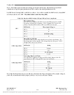
For 48V operation both jumpers must be in the 48V position. For 125V operation both jumpers
must be in the 125V position. The 250V modules should have both jumpers in the 125V position.
See Table 5-11.
RFL 9508D UCC
RFL Electronics Inc.
May 27, 2011
5-22
(973) 334-3100


