Applications
RFL 9508D UCC
RFL Electronics Inc.
Section 2.
2.1.1
APPLICATIONS
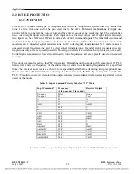
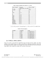
This section discusses typical RFL 9508D applications, PLC-TT applications and Tx and Rx Filter
performance. It also discusses Line Board applications and Analog Level considerations and
calculations.
2.1
RFL 9508D APPLICATIONS
POINT-TO-POINT APPLICATION
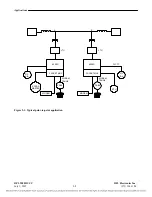
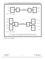
Figure 2-1 illustrates a typical point-to-point application with one SCADA (Supervisory Control And
Data Acquisition) channel, one Data channel (Modem), and one speech channel transmitted through
the digital link, Additionally it has integrated type F6 teleprotection.
When RF channel 2 is configured for speech plus operation, the speech band is terminated at 2000Hz
(programmable), and the bandwidth above 2100Hz (programmable), can be used for one (as shown) or
more slow speed data channels using external modem(s).
Modem signal is transmitted through a 2W or 4W E&M channel in the bandwidth from 300 to
3400Hz.
For this point-to-Point application, the speech channel provides the link for the PABX at each
substation interconnecting them, so expanding the phone network.
Each 9508D terminal at nodes A and B is connected to the power line via an LTU (Line Tuning Unit)
and coupling capacitor (CC). The LTU matches the characteristic (surge) impedance of the power line
to the impedance of the 9508D terminal. The LTU also contains a surge arrestor to protect the
equipment from voltage spikes, lightning or other faults. The coupling capacitor isolates the 9508D
from the high voltage of the power line.
The SCADA master is used to monitor and manage electrical power distribution facilities. It is shown
connected to the packetizing multiplexer of the 9508D at node A. The SCADA remote (Remote
Terminal Unit or RTU) is shown connected to the packetizing multiplexer of the 9508 at node B. The
SCADA master communicates with the RTU over the RFL 9508D power line carrier link at data rates
of 9600 baud and higher depending only on the availability of bandwidth in the digital link..
A 21P device is shown at nodes A and B. The 21 indicates that the device is a distance (under
impedance) relay. The P indicates that there is a pilot channel communication link. In this example the
RFL 9508D equipment provides the pilot channel. The A-B indicates that the communication channel
is from node A to node B. Conversely, the B-A indicates that the communication channel is from node
B to node A.
When the overreaching 21P distance relay detects a fault in the forward direction, it provides a contact
closure to the PLC-TT module at the local end. The PLC-TT module sends the contact closure
information to the remote end PLC-TT module over the 9508D power line carrier link. The PLC-TT
module can support up to four bi-directional transfer trip functions (two permissive and/or two direct)
between two terminals or can support DCB (Directional Comparison Blocking) in addition to two
Transfer Trip Functions.
July 1, 2007
2-1
(973) 334.3100


