Module Descriptions, RFL 9508D Digital Section
8.11
POWER SUPPLY ALARM I/O MODULE
8.11.1
DESCRIPTION
1
0
1
0
!
P.S. DIGITAL
ON
OFF
P.S. RF
COM
NC
NO
COM
NC
NO
OFF
F1
6A
F2
6A
ON
AL
ARM
AL
ERT
+
-
+
RF
-
RF
SB
RG
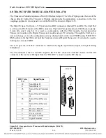
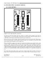
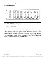
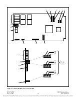
Figure 8-17. Power Supply Alarm I/O, rear panel view
The function of the Power Supply Alarm I/O module is to respond to fault conditions on the CM4, on
channel modules, or on the power supply module itself. The Power Supply Alarm I/O module consists of
an EMI filter, an SWC filter, an alarm relay and an alert relay, and relay logic.
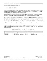
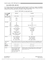
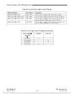
There are four types of Power Supply Alarm I/O modules that can be used with the RFL 9508D chassis.
Some of the characteristics of these modules are listed in Table 8-18. A rear panel view of the 9547-18809
Power Supply Alarm I/O module is shown in Figure 8-17.
When a Main Shelf is equipped with a main power supply and a redundant power supply it will have only
one Power Supply Alarm I/O module. The relays on the Power Supply Alarm I/O module will respond to
alarm and alert conditions from both power supply modules. This insures that Alarm and/or Alert
monitoring continues even if one or the other supply is removed. Note that because the corresponding relay
contacts on the Main and Redundant supplies are connected in parallel, the ACO switches on both must be
switched “on” to activate the alarm cut-off, and both must be switched “off” to de-activate the alarm cut-
off.
Each Alarm I/O module operates with a specific Power Supply module. Refer to Table 8-19 for Power
Supply Alarm I/O application information. Only one Power Supply Alarm I/O module is used per chassis.
RFL 9508D UCC
RFL Electronics Inc.
March 11, 2010
8-40
(973) 334-3100

