


3. SIGNALS AND WIRING
3 - 59
3.9.3 Source I/O interfaces
In this servo amplifier, source type I/O interfaces can be used.
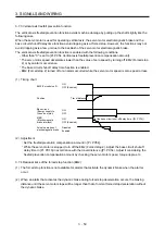
(1) Digital input interface DI-1
This is an input circuit whose photocoupler anode side is the input terminal. Transmit signals from
source (open-collector) type transistor output, relay switch, etc.
Approximately
6.2 k
Ω
24 V DC ± 10%
300 mA
Switch
For transistor
EM2
etc.
Servo amplifier
DICOM
Approximately
5 mA
V
CES
≤
1.0 V
I
CEO
≤
100 µA
TR
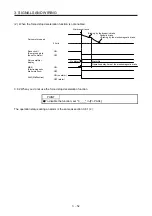
The following shows when the CN1-37 pin and the CN1-38 pin are used as digital input interface:
Approximately
1.2 k
Ω
Servo amplifier
PP2
(CN1-37)
PG
Switch
Approximately
1.2 k
Ω
NP2
(CN1-38)
NG
SD
24 V DC ± 10%
300 mA
Switch
(2) Digital output interface DO-1
This is a circuit in which the emitter of the output transistor is the output terminal. When the output
transistor is turned on, the current will flow from the output terminal to a load.
A maximum of 2.6 V voltage drop occurs in the servo amplifier.
(Note) 24 V DC ± 10%
300 mA
Servo amplifier
ALM
etc.
DOCOM
Load
If polarity of diode is
reversed, servo amplifier
will malfunction.
Note. If the voltage drop (maximum of 2.6 V) interferes with the relay operation, apply high
voltage (maximum of 26.4 V) from external source.
Содержание MR-JE-_A
Страница 9: ...A 8 MEMO ...
Страница 15: ...6 MEMO ...
Страница 29: ...1 FUNCTIONS AND CONFIGURATION 1 14 MEMO ...
Страница 139: ...4 STARTUP 4 38 MEMO ...
Страница 187: ...5 PARAMETERS 5 48 MEMO ...
Страница 221: ...6 NORMAL GAIN ADJUSTMENT 6 34 MEMO ...
Страница 259: ...8 TROUBLESHOOTING 8 8 MEMO ...
Страница 264: ...9 DIMENSIONS 9 5 2 SCR connector system 3M Receptacle 36210 0100PL Shell kit 36310 3200 008 Unit mm 34 8 39 5 22 4 11 0 ...
Страница 265: ...9 DIMENSIONS 9 6 MEMO ...
Страница 273: ...10 CHARACTERISTICS 10 8 MEMO ...
Страница 339: ...12 COMMUNICATION FUNCTION MITSUBISHI ELECTRIC GENERAL PURPOSE AC SERVO PROTOCOL 12 34 MEMO ...


