4. STARTUP
4 - 4
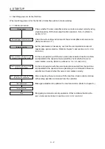
(2) I/O signal wiring
(a) The I/O signals should be connected correctly.
Use DO forced output to forcibly turn on/off the pins of the CN1 connector. You can use the function
to check the wiring. Switch off SON (Servo-on) to enable the function.
Refer to section 3.2 for details of I/O signal connection.
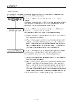
(b) A voltage exceeding 24 V DC is not applied to the pins of the CN1 connector.
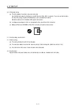
(c) Between Plate and DOCOM of the CN1 connector should not be shorted.
Servo amplifier
DOCOM
Plate
CN1
4.1.3 Surrounding environment
(1) Cable routing
(a) The wiring cables should not be stressed.
(b) The encoder cable should not be used in excess of its bending life. (Refer to section 10.4.)
(c) The connector of the servo motor should not be stressed.
(2) Environment
Signal cables and power cables are not shorted by wire offcuts, metallic dust or the like.
Содержание MR-JE-_A
Страница 9: ...A 8 MEMO ...
Страница 15: ...6 MEMO ...
Страница 29: ...1 FUNCTIONS AND CONFIGURATION 1 14 MEMO ...
Страница 139: ...4 STARTUP 4 38 MEMO ...
Страница 187: ...5 PARAMETERS 5 48 MEMO ...
Страница 221: ...6 NORMAL GAIN ADJUSTMENT 6 34 MEMO ...
Страница 259: ...8 TROUBLESHOOTING 8 8 MEMO ...
Страница 264: ...9 DIMENSIONS 9 5 2 SCR connector system 3M Receptacle 36210 0100PL Shell kit 36310 3200 008 Unit mm 34 8 39 5 22 4 11 0 ...
Страница 265: ...9 DIMENSIONS 9 6 MEMO ...
Страница 273: ...10 CHARACTERISTICS 10 8 MEMO ...
Страница 339: ...12 COMMUNICATION FUNCTION MITSUBISHI ELECTRIC GENERAL PURPOSE AC SERVO PROTOCOL 12 34 MEMO ...


