5. PARAMETERS
5 - 32
No./symbol/
name
Setting
digit
Function
Initial
value
[unit]
Control mode
P S T
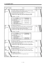
PC13
TLC
Analog torque
command
maximum
output
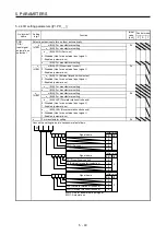
Set the output
torque at the analog torque command voltage (TC = ±8 V) of +8 V on
the assumption that the maximum torque is 100.0%.
For example, set 50.0.
The maximum torque ×
50.0
100.0
is outputted.
If a value equal to or larger than the maximum torque is inputted to TC, the value is
clamped at the maximum torque.
Setting range: 0.0 to 1000.0
100.0
[%]
PC14
MOD1
Analog
monitor 1
output
_ _ x x Analog monitor 1 output selection
Select a signal to output to MO1 (Analog monitor 1). Refer to app. 3 (3) for detection
point of output selection.
Refer to table 5.8 for settings.
00h
_ x _ _ For manufacturer setting
0h
x _ _ _
0h
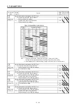
Table 5.8 Analog monitor setting value
Setting
value
Item
_ _ 0 0
Servo motor speed (±8 V/max. speed)
(Note 3)
_ _ 0 1
Torque (±8 V/max. torque) (Note 2)
_ _ 0 2 Servo motor speed (+8 V/max. speed) (Note 3)
_ _ 0 3 Torque (+8 V/max. torque) (Note 2)
_ _ 0 4
Current command (±8 V/max. current command)
_ _ 0 5
The command pulse frequency (±10 V/4
Mpulses/s)
_ _ 0 6 Servo motor-
side droop pulses (±10 V/100 pulses) (Note 1)
_ _ 0 7 Servo motor-
side droop pulses (±10 V/1000 pulses) (Note 1)
_ _ 0 8 Servo motor-
side droop pulses (±10 V/10000 pulses) (Note 1)
_ _ 0 9 Servo motor-
side droop pulses (±10 V/100000 pulses) (Note 1)
_ _ 0 D Bus voltage (+8 V/400 V)
_ _ 0 E
Speed command 2 (±8 V/max. speed)
(Note 3)
_ _ 1 7 Internal temperature of encoder
(±10 V/±128
°C)
Note 1. Encoder pulse unit
2. The value in [Pr. PA11] or [Pr. PA12] whichever higher is applied for the maximum torque.
3. The maximum speed of the HF-KN series servo motor is 4500 r/min and that of the HG-KN series
is 5000 r/min. Please watch out when using an HG-KN series servo motor as a replacement for
the HF-KN series servo motor because HG-KN series output 8 V at 5000 r/min. HG-KN series
servo motors output 8 V at 6000 r/min when you set "_ _ _ 1" in [Pr. PA28] to change the
maximum speed to 6000 r/min.
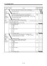
PC15
MOD2
Analog
monitor 2
output
_ _ x x Analog monitor 2 output selection
Select a signal to output to MO2 (Analog monitor 2). Refer to app. 3 (3) for detection
point of output selection.
Refer to [Pr. PC14] for settings.
01h
_ x _ _ For manufacturer setting
0h
x _ _ _
0h
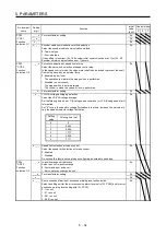
PC16
MBR
Electromagne
tic brake
sequence
output
Set the delay time between MBR (Electromagnetic brake interlock) and the base
drive circuit is shut-off.
Setting range: 0 to 1000
0
[ms]
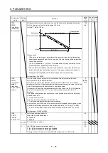
PC17
ZSP
Zero speed
Set the output range of ZSP (Zero speed detection).
ZSP (Zero speed detection) has hysteresis of 20 r/min.
Setting range: 0 to 10000
50
[r/min]
Содержание MR-JE-_A
Страница 9: ...A 8 MEMO ...
Страница 15: ...6 MEMO ...
Страница 29: ...1 FUNCTIONS AND CONFIGURATION 1 14 MEMO ...
Страница 139: ...4 STARTUP 4 38 MEMO ...
Страница 187: ...5 PARAMETERS 5 48 MEMO ...
Страница 221: ...6 NORMAL GAIN ADJUSTMENT 6 34 MEMO ...
Страница 259: ...8 TROUBLESHOOTING 8 8 MEMO ...
Страница 264: ...9 DIMENSIONS 9 5 2 SCR connector system 3M Receptacle 36210 0100PL Shell kit 36310 3200 008 Unit mm 34 8 39 5 22 4 11 0 ...
Страница 265: ...9 DIMENSIONS 9 6 MEMO ...
Страница 273: ...10 CHARACTERISTICS 10 8 MEMO ...
Страница 339: ...12 COMMUNICATION FUNCTION MITSUBISHI ELECTRIC GENERAL PURPOSE AC SERVO PROTOCOL 12 34 MEMO ...


