4
8. TROUBLESHOOTING
8- 1 to 8- 8
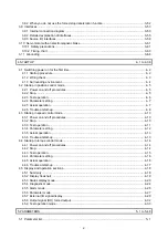
8.1 Explanations of the lists .................................................................................................................... 8- 1
8.2 Alarm list ........................................................................................................................................... 8- 2
8.3 Warning list ....................................................................................................................................... 8- 6
9. DIMENSIONS
9- 1 to 9- 6
9.1 Servo amplifier .................................................................................................................................. 9- 1
9.2 Connector ......................................................................................................................................... 9- 4
10. CHARACTERISTICS
10- 1 to 10- 8
10.1 Overload protection characteristics .............................................................................................. 10- 1
10.2 Power supply capacity and generated loss .................................................................................. 10- 2
10.3 Dynamic brake characteristics ...................................................................................................... 10- 4
10.3.1 Dynamic brake operation ....................................................................................................... 10- 5
10.3.2 Permissible load to motor inertia when the dynamic brake is used ....................................... 10- 6
10.4 Cable bending life ......................................................................................................................... 10- 6
10.5 Inrush current at power-on ........................................................................................................... 10- 7
11. OPTIONS AND PERIPHERAL EQUIPMENT
11- 1 to 11-32
11.1 Cable/connector sets .................................................................................................................... 11- 1
11.1.1 Combinations of cable/connector sets ................................................................................... 11- 2
11.2 Regenerative option ...................................................................................................................... 11- 4
11.2.1 Combination and regenerative power .................................................................................... 11- 4
11.2.2 Selection of regenerative option ............................................................................................ 11- 5
11.2.3 Parameter setting ................................................................................................................... 11- 6
11.2.4 Connection of regenerative option ......................................................................................... 11- 7
11.2.5 Dimensions ........................................................................................................................... 11-11
11.3 Junction terminal block MR-TB50 ................................................................................................ 11-13
11.4 MR Configurator2 ........................................................................................................................ 11-15
11.4.1 Specifications ........................................................................................................................ 11-15
11.4.2 System requirements ............................................................................................................ 11-16
11.4.3 Precautions for using USB communication function ............................................................. 11-17
11.5 Selection example of wires .......................................................................................................... 11-18
11.6 Molded-case circuit breakers, fuses, magnetic contactors ......................................................... 11-19
11.7 Power factor improving AC reactor .............................................................................................. 11-20
11.8 Relay (recommended) ................................................................................................................. 11-21
11.9 Noise reduction techniques ......................................................................................................... 11-22
11.10 Earth-leakage current breaker ................................................................................................... 11-28
11.11 EMC filter (recommended) ........................................................................................................ 11-30
12. COMMUNICATION FUNCTION (MITSUBISHI ELECTRIC GENERAL-PURPOSE AC SERVO PROTOCOL)
12- 1 to 12-34
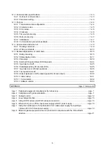
12.1 Structure ....................................................................................................................................... 12- 1
12.1.1 Configuration diagram ............................................................................................................ 12- 1
12.1.2 Precautions for using RS422/USB communication function .................................................. 12- 2
Содержание MR-JE-_A
Страница 9: ...A 8 MEMO ...
Страница 15: ...6 MEMO ...
Страница 29: ...1 FUNCTIONS AND CONFIGURATION 1 14 MEMO ...
Страница 139: ...4 STARTUP 4 38 MEMO ...
Страница 187: ...5 PARAMETERS 5 48 MEMO ...
Страница 221: ...6 NORMAL GAIN ADJUSTMENT 6 34 MEMO ...
Страница 259: ...8 TROUBLESHOOTING 8 8 MEMO ...
Страница 264: ...9 DIMENSIONS 9 5 2 SCR connector system 3M Receptacle 36210 0100PL Shell kit 36310 3200 008 Unit mm 34 8 39 5 22 4 11 0 ...
Страница 265: ...9 DIMENSIONS 9 6 MEMO ...
Страница 273: ...10 CHARACTERISTICS 10 8 MEMO ...
Страница 339: ...12 COMMUNICATION FUNCTION MITSUBISHI ELECTRIC GENERAL PURPOSE AC SERVO PROTOCOL 12 34 MEMO ...


