10. CHARACTERISTICS
10 - 2
1000
100
10
1
0.1
100
200
300
0
50
150
250
320
Operation time [s]
Servo-lock
Operating
(Note) Load ratio [%]
HG-SN152_/HG-SN202_/HG-SN302_
Note. If operation that generates torque more than 100% of the rating is performed with an abnormally high frequency in a servo motor
stop status (servo-lock status) or in a 50 r/min or less low-speed operation status, the servo amplifier may malfunction regardless
of the electronic thermal protection.
Fig. 10.1 Electronic thermal protection characteristics
10.2 Power supply capacity and generated loss
(1) Amount of heat generated by the servo amplifier
Table 10.1 indicates servo amplifiers' power supply capacities and losses generated under rated load.
For thermal design of an enclosed type cabinet, use the values in the table in consideration for the worst
operating conditions. The actual amount of generated heat will be intermediate between values at rated
torque and servo-off according to the duty used during operation. When the servo motor is run at less
than the rated speed, the power supply capacity will be smaller than the value in the table, but the servo
amplifier's generated heat will not change.
Table 10.1 Power supply capacity and generated loss per servo motor at rated output
Servo amplifier
Servo motor
(Note 1)
Power supply
capacity [kVA]
(Note 2) Servo amplifier-
generated heat [W]
Area required
for heat
dissipation [m
2
]
At rated output
With servo-off
MR-JE-10A HG-KN13_
0.3
25
15
0.5
MR-JE-20A HG-KN23_
0.5
25
15
0.5
MR-JE-40A HG-KN43_
0.9
35
15
0.7
MR-JE-70A
HG-KN73_ 1.3
50
15
1.0
HG-SN52_ 1.0
40
15
0.8
MR-JE-100A HG-SN102_
1.7
50
15
1.0
MR-JE-200A
HG-SN152_ 2.5
90 20 1.8
HG-SN202_ 3.5
MR-JE-300A HG-SN302_
4.8
120
20
2.4
Note 1. The power supply equipment capacity changes with the power supply impedance. This value is
applicable when the power factor improving AC reactor is not used.
2. Heat generated during regeneration is not included in the servo amplifier-generated heat. To calculate
heat generated by the regenerative option, refer to section 11.2.
Содержание MR-JE-_A
Страница 9: ...A 8 MEMO ...
Страница 15: ...6 MEMO ...
Страница 29: ...1 FUNCTIONS AND CONFIGURATION 1 14 MEMO ...
Страница 139: ...4 STARTUP 4 38 MEMO ...
Страница 187: ...5 PARAMETERS 5 48 MEMO ...
Страница 221: ...6 NORMAL GAIN ADJUSTMENT 6 34 MEMO ...
Страница 259: ...8 TROUBLESHOOTING 8 8 MEMO ...
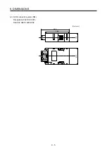
Страница 264: ...9 DIMENSIONS 9 5 2 SCR connector system 3M Receptacle 36210 0100PL Shell kit 36310 3200 008 Unit mm 34 8 39 5 22 4 11 0 ...
Страница 265: ...9 DIMENSIONS 9 6 MEMO ...
Страница 273: ...10 CHARACTERISTICS 10 8 MEMO ...
Страница 339: ...12 COMMUNICATION FUNCTION MITSUBISHI ELECTRIC GENERAL PURPOSE AC SERVO PROTOCOL 12 34 MEMO ...


