background image


5-96 Image Optimization 

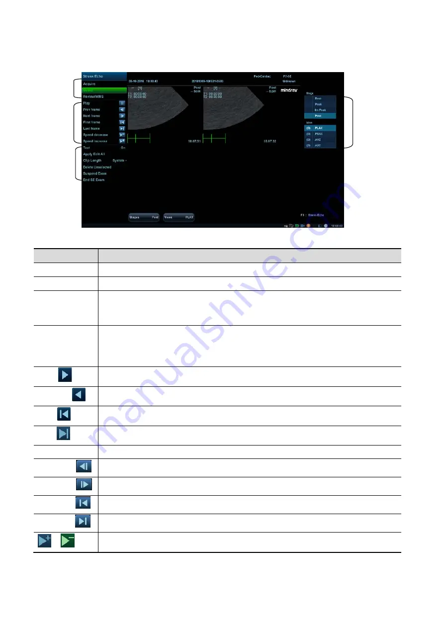
Description of select mode controls: 


Touch screen controls: 

Selection 

Description 

Stages: XX 

Rotate the corresponding knob under the button to select a stage. 

Views: XX 

Rotate the corresponding knob under the button to select a view. 

Acquire/   

Select/ 
Review/WMS 

To switch the mode status. 

1. Clip 
/2. Clip 
/3. Clip 
/4. Clip 

For selecting views in the selected stage.   

Next 


Next four Clips. 

Previous 


Previous four Clips. 

First 


Go to “first” Clips. 

Last 


Go to “last” Clips. 

Play 

Click to play/stop cine play. 

Prev frame


See previous frame of the cine file. 

Next frame


See next frame of the cine file. 

First frame


See first frame of the cine file. 

Last frame


See last frame of the cine file. 

  / 


Decreases or increases playback speed. 

Phase/view 
selection 

Cine 
controls 

Other 
controls 

Mode 

Содержание DC-80A

Страница 1: ...DC 90 DC 90S DC 90Q DC 95 DC 95S DC 88 DC 88S DC 80A DC 80A Exp DC 80A Pro DC 8X DC 8Q DC 81 DC 82 Diagnostic Ultrasound System Operator s Manual Basic Volume...

Страница 2: ......

Страница 3: ...2 System Overview 2 1 2 1 Intended Use 2 1 2 2 Contraindication 2 1 2 3 Product and Model Code 2 1 2 4 Product Specifications 2 2 2 5 System Configuration 2 3 2 6 Introduction of Each Unit 2 9 2 7 I...

Страница 4: ...Cine Review 6 1 6 1 Splitting Display 6 1 6 2 Image Magnification 6 1 6 3 Freeze Unfreeze the Image 6 2 6 4 Cine Review 6 3 6 5 Image Compare 6 6 6 6 Cine Saving 6 7 6 7 Setting Cine Length 6 7 7 Phy...

Страница 5: ...13 Probes and Biopsy 13 1 13 1 Probes 13 1 13 2 Biopsy Guide 13 15 13 3 Middle Line 13 43 14 DVR Recording 14 1 14 1 DVR Recording 14 1 14 2 Send Image 14 1 14 3 DVR Video Replay 14 2 15 Acoustic Out...

Страница 6: ...iv Appendix D Wireless LAN D 1 Appendix E Battery E 1 Appendix F Ultrasound Gel Warmer F 1 Appendix G Electrical Safety Inspection G 1...

Страница 7: ...en and are the trademarks registered or otherwise of Mindray in China and other countries All other trademarks that appear in this manual are used only for informational or editorial purposes They are...

Страница 8: ...ortation or other charges or liability for direct indirect or consequential damages or delay resulting from the improper use or application of the product or the use of parts or accessories not approv...

Страница 9: ...12th Road South High tech industrial park Nanshan Shenzhen 518057 P R China Website www mindray com E mail Address service mindray com Tel 86 755 81888998 Fax 86 755 26582680 Manufacturer Mindray DS...

Страница 10: ...not be liable for the results of diagnostic procedures 7 Important data must be backed up on external memory media 8 Mindray shall not be liable for loss of data stored in the memory of this system ca...

Страница 11: ...t etc Operator s Manual Advanced Volume Operator s Manual Acoustic Power Data and Surface Temperature Data Contains data tables of acoustic output for transducers Operation Note Contains a quick guide...

Страница 12: ...buttons in dialog box square brackets indicate items in menus on the soft menu or buttons in dialog boxes Click Items or Buttons move the cursor to the item or button and press Set or use the soft ke...

Страница 13: ...and sterilization method s recommended by manufacturer Equipment with disinfection and sterilization method s recommended by manufacturer According to the degree of safety of application in the presen...

Страница 14: ...ates a potentially hazardous situation that if not avoided may result in minor or moderate injury NOTE Indicates a potentially hazardous situation that if not avoided may result in property damage Des...

Страница 15: ...meets the requirement of the local medical device electrical regulations e g the touch leakage current should be no more than 500uA as per IEC 60601 1 in Chapter 16 and the responsibility is held by t...

Страница 16: ...vices Do not connect other devices to the outlet The rated output power limitation may be exceeded and this may lead to failure The maximum output power of the outlet is 240VA 18 Additional equipment...

Страница 17: ...y this equipment without authorization of the manufacturer 26 Always read and follow carefully the manufacturer instructions on the contrast agent label 27 When using an intra cavity probe pay attenti...

Страница 18: ...or may fall and result in injury to individuals Fasten and fully secure any peripheral devices before moving the system Loose peripheral devices may fall and result in injury to individuals When movin...

Страница 19: ...t with the relevant local regulations 15 Read the Acoustic Output Principle in the operation manual carefully before operating this system in clinical examinations 16 The cover contains natural rubber...

Страница 20: ...and free air exchange 11 To dispose of the system or any part thereof contact the Mindray Customer Service Department or a sales representative Mindray is not responsible for any system content or acc...

Страница 21: ...oes not become a source of infection 3 In normal diagnostic ultrasound mode there is no danger of a normal temperature burn However keeping the probe on the same region of the patient for a prolonged...

Страница 22: ...o may result in the ultrasound gel solidifying and the image quality being degraded Repeated disinfection will eventually damage the probe Check the probe s performance periodically 1 5 Latex Alert Wh...

Страница 23: ...h warning label are described as follows No Warning Labels Meaning 1 a Do not place the system on a sloped surface Otherwise the system may slide resulting in personal injury or the system malfunction...

Страница 24: ......

Страница 25: ...use in fetal abdominal pediatric small organ breast thyroid testes neonatal and adult cephalic trans rectal trans vaginal musculo skeletal conventional superficial adult and pediatric cardiac periphe...

Страница 26: ...s M Free Xros CM C Mode Color Power DirPower D Mode PW CW Special imaging Smart 3D Static 3D 4D Color 3D Color M iScape panoramic imaging TDI Tissue Doppler imaging TDI QA Stress Echo Tissue Tracking...

Страница 27: ...8 inch monitor folded 825 5mm Length 510 5mm main unit 575 5mm display Width 1090 5mm Height Weight including batteries 85KG 2 5 System Configuration 2 5 1 Standard Configuration Main unit System sof...

Страница 28: ...urface L20 5E Linear Small Organ breast thyroid testes Musculo skeletal conventional superficial Peripheral vessel Body surface DE11 3E Volume Fetal Trans rectal Trans vaginal Transvaginal SC5 1NE Con...

Страница 29: ...CIVCO 658 001 V11 3HE CIVCO 610 543 CIVCO 610 1274 2 5 3 Options No Item Remarks 1 ECG 2 DC IN cable ECG module should be configured 3 Three cable lead ECG module should be configured 4 Built in Batte...

Страница 30: ...be configured 35 LVO Cardiology Package should be configured 36 Smart Planes CNS Obstetrics Package and 4D module should be configured 37 Smart Face Obstetrics Package and 4D module should be configur...

Страница 31: ...58 Nerve Package 59 Emergency Critical Package 60 IMT Vascular Package should be configured 61 Smart NT Obstetrics Package should be configured 62 IVF Gynecology Package should be configured 63 Smart...

Страница 32: ...e DVR Parts that can be used within patient environment Main unit Probes Footswitch Printers NOTE If the ultrasound system cannot recognize the SONY UP X898MD printer automatically you may need to cha...

Страница 33: ...pencil probe 7 Probe cable hook Used for fixing the probe cable 8 Keyboard Used for typing characters or entering some functions 9 Main control panel Operator system interface or control 10 Control p...

Страница 34: ...r for adjusting the height and position of the monitor 20 Rear handle Used for pushing and moving the system 21 Supporting arm locking lever Used for locking unlocking the supporting arm 22 Cooling ve...

Страница 35: ...al output port left channel Audio signal output port right channel 7 8 12V power indicator 9 5V power indicator 10 3 3V power indicator 11 PC_LVDS indicator 12 PHV protection indicator NOTE 1 The S VI...

Страница 36: ...Function 1 Power outlet Supplies power to optional peripheral devices 2 Power inlet AC power inlet 3 Equipotential terminal Used for equipotential bonding which balances the protective earth potential...

Страница 37: ...ecting a pencil probe 3 MIC port Used for connecting a microphone 4 ECG lead signal input port external ECG signal input port Connects to ECG leads to directly obtain the patient s ECG signals Connect...

Страница 38: ...status and the indicator becomes green 2 Volume Adjust the volume 3 Adjust the corresponding functions on the touch screen 4 5 6 7 8 TGC Slide to adjust the depth gain 9 Patient Enter exit Patient Inf...

Страница 39: ...the two display windows in the Dual mode 24 B Press to enter B mode and rotate to adjust B mode gain 25 Single Enter single window in multiple window mode 26 4D Press to enter 4D function and rotate t...

Страница 40: ...ly Discharging status It illuminates in green when the power of the batteries is sufficient It illuminates in orange for low battery capacity AC indicator The indicator is on at AC supply Standby indi...

Страница 41: ...Patient Info system 3 F3 F6 User defined keys the functions of which can be preset 4 F7 QSave Save the current image parameters quickly 5 F8 iZoom Enter exit full screen zoom status 6 F9 DVR Reserved...

Страница 42: ...s indicated with a frame on the key No Fn Name Function 1 End Move the cursor to the end of the row or the rightmost side of an editable unit 2 Home Home 3 Pg Up Turn pages upward 4 Pg Dw Turn pages d...

Страница 43: ...Reserved used for separate video output AUDIO Used for stereo audio output HDMI High definition multimedia interface Microphone input jack When the lever located at the bottom of the monitor supporti...

Страница 44: ......

Страница 45: ...ose permitted by Mindray ensure the overall leakage current of peripherals and the ultrasound system meets the requirement of the local medical device electrical regulations e g the enclosure leakage...

Страница 46: ...d to lock the power cord as shown in the figure above 3 Plug the power plug at the other end into an appropriate outlet The grounding terminal should be connected with a power grounding cable to ensur...

Страница 47: ...in electric shock 2 When you connect another device to this system you should use the equipotential wire to connect each of equipotential terminals Failure to do so may result in electric shock 3 Con...

Страница 48: ...on damage or dirt on the system and peripheral devices If any dirt is found cleaning shall be performed as illustrated in section 17 System Maintenance 4 There are no loose screws on the monitor or co...

Страница 49: ...me as the system date and time and are displayed correctly WARNING If you use a probe giving off excessive heat it may burn the patient If you find anything not functioning properly this may indicate...

Страница 50: ...ver delay period If there is still no operation the system enters standby after the standby delay period Press the power button and select Standby the system enters standby mode To exit standby Press...

Страница 51: ...and forth to adjust the displacement NOTE Take care not to trap your hands when adjusting the monitor up and down Rotate the monitor The monitor can turn left 90 degrees to the right 150 degrees along...

Страница 52: ...hin a short distance for example move to other department turn the monitor to the horizontal level push it to the locking structure and then the monitor can be locked For more details please refer to...

Страница 53: ...amage 4 Only use probes provided by Mindray Aftermarket probes may result in damage or cause a fire NOTE If a probe port is not used for a long period of time use the dustproof cover to protect the pr...

Страница 54: ...vices WARNING DO NOT directly remove a USB memory device as the USB device and or the system may become damaged When connecting a USB memory device to the ultrasound system via a USB port a sound is h...

Страница 55: ...System Preparation 3 11 Function setting The function of the foot switch can be preset For details see 12 1 6 Key Configuration...

Страница 56: ...n the service list You can select printer from the driver list next to Printer in the lower screen and set the items in the Property box Click Save after you have finished setting Please refer to the...

Страница 57: ...ck Save to complete 3 7 3 Position the Printer As shown in the following figure you can open the video printer compartment gate and then place the black white digital video printer in the video printe...

Страница 58: ...3 14 System Preparation Uninstalling Press the clip in the direction of the arrow to get out the holder...

Страница 59: ...System Preparation 3 15...

Страница 60: ...int area Soft menu parameter window User defined key and gesture hint area Help Information System Status Icon Patient Exam information The Information area consists of the hospital name patient name...

Страница 61: ...epth time velocity frequency and focal position located on the depth axis in the form of Annotations body marks measurement calipers color bar grayscale bar are also displayed here Image parameter are...

Страница 62: ...a certain area on the monitor using the trackball Results window Comments area Body marks area 3 8 2 Basic Operations of the Dialog Box A dialog box screen consists of a title page tabs contents and b...

Страница 63: ...ifferent modes display in real time in the top left corner of the screen For details of measurement menu operations see the Advanced Volume Operate the menu using the trackball and left right Set key...

Страница 64: ...t for details Under mapping non mapping mode you can do fast operation using two finger gesture according to the gesture hints on the bottom right of the screen 4 Under mapping mode swipe from this ar...

Страница 65: ...e rotate the knobs beneath the touch screen to show the soft menu Rotate the knob to complete the adjustment Two finger gesture For details about two finger gesture function setting see 12 1 6 Key Con...

Страница 66: ...the current image Exit mapping mode Swipe the touch screen from bottom to top to exit the mapping mode Non mapping mode of touch screen The layout of the touch screen varies with the applications or m...

Страница 67: ...System Preparation 3 23...

Страница 68: ......

Страница 69: ...information 4 1 Patient Information To start a new patient exam it is best to enter detailed patient information The system will set up a unique information database for each patient based on the pat...

Страница 70: ...is not permitted The ID can also be obtained using the bar code reader Name Enter the patient s name using the keyboard Gender Select Male Female or Unknown for patient gender from the drop down list...

Страница 71: ...formula which is set via Setup System General BMI After the height and weight are input the system will automatically calculate the Body Mass Index Fasting ALT Alanine transaminase OB Obstetrics Heigh...

Страница 72: ...f abortion IVF Info Female hormone basic level and drugs inducing the ovulation CARD Cardiology Height Weight BSA body surface area After the height and weight are entered the system will automaticall...

Страница 73: ...A canceled exam cannot be restored New Patient clears the current patient information in the patient information screen so new patient information can be entered New Exam clears the current exam infor...

Страница 74: ...ll search on the keyword in the existing searched results 4 Select the desired patient information in the list and the system brings up the following menu Button Function Description Review an Image C...

Страница 75: ...ms Click to continue an exam that has been completed within 24 hours Resume Exams Click to continue an exam that has been paused within 24 hours Other buttons New Exam click to enter the Patient Info...

Страница 76: ...erver 4 Enter the search condition a Input the searching condition Select DICOM server You can search via patient ID accession key words AE title worklist server or exam date Select HL7 server Search...

Страница 77: ...he patient information is imported into the Patient Info screen After editing the patient information in the Patient Info screen select OK to start a new exam c Click Show Detail to see details of pat...

Страница 78: ...obe switch can be defined in preset by which you can fast switch the probe under B Color Power mode This function applies only to probes with the same exam modes 1 Scan to obtain the image by current...

Страница 79: ...m s patient database For an activated exam you can modify the patient ID if this patient has only one exam recorded in the system 4 5 Pause End an Exam 4 5 1 Pause an Exam Sometimes it is necessary to...

Страница 80: ......

Страница 81: ...Imaging Modes Switch between imaging modes according to the actual situation See 2 10 Control Panel for details 5 1 2 Image Adjustment Adjust using the image menu For details about menu adjustment see...

Страница 82: ...on the current menu Press or rotate the knobs to adjust the corresponding parameters Adjust using the touch screen mapping mode 1 Enter the mapping mode to see the following mapping menu See 3 8 4 To...

Страница 83: ...eter settings Enter the name in the box after Save As to assign a name for a user defined exam mode and click Create to save the current image parameters measurements comments and body mark settings t...

Страница 84: ...to select the different fundamental harmonic frequency values Press the knob to switch between fundamental frequency and harmonic frequency The adjusting range of the fundamental frequency values can...

Страница 85: ...ects Adjust the signal gain for a particular image area to achieve a balanced image Acoustic Power Description Refers to the power of ultrasonic waves transmitted by the probe the real time value of w...

Страница 86: ...as extending the scanning angle Impacts The FOV position range is available only for convex and phase probes The ExFOV function is available only for linear and convex probes The B Steer function is...

Страница 87: ...vides 0 7 levels of frame average adjustment the bigger the value the stronger the effect Effects Persistence can remove image noise to make details clearer Impacts Increasing Persistence may lead to...

Страница 88: ...escription This function provides an imaging process based on color difference rather than gray distinction Operations Rotate the knob under the Tint Map item or the mapping menu item on the touch scr...

Страница 89: ...ge magnification is available in dual live mode LGC Description Adjust the gain of scan lines to increase the image lateral resolution Operation Touch LGC or the mapping menu item on the touch screen...

Страница 90: ...can then observe the tissue motion along with the anatomical images of B mode During the scanning process you can also adjust the sampling line accordingly when necessary 4 Adjust the image parameters...

Страница 91: ...on This function is used to set the scanning speed of M mode imaging and the real time speed value is displayed in the image parameter area in the top right corner of the screen Operations Rotate the...

Страница 92: ...s used to process the scan lines of M images to reject noise making image details clearer Operations Adjust using the M Soften item or the mapping menu item on the touch screen The system provides 4 l...

Страница 93: ...y PRF Color Wall Filter During Color mode imaging the image optimizing menus for B mode and Color mode are displayed on the touch screen at the same time You can switch between the 2 modes by clicking...

Страница 94: ...g to probe types Select the frequency according to the needs of the detection depth and the current tissue characteristics B C Align Description To set and restrict the maximum width of the B mode ima...

Страница 95: ...e sensitivity Effects The higher the packet size the more sensitive the indication for low velocity flow Impacts Adjusting the packet size may lead to the frame rate changing Flow State Description Th...

Страница 96: ...isplay Operations Rotate the knob under Baseline on the touch screen or the mapping menu item on the touch screen A positive value means increase the signals above the baseline and a negative value me...

Страница 97: ...n is used to set the levels of the flow display and to display the grayscale signal or color signal Operations Rotate the knob under the Priority item or the mapping menu item on the touch screen to s...

Страница 98: ...ion Power mode provides a non directional display of the blood flow in terms of intensity as opposed to flow velocity DirPower Directional Power mode provides additional information of the flow direct...

Страница 99: ...0 100 in increments of 2 Effects Increasing the gain will increase the flow signal presented and noise The signals may be missing when the gain is adjusted too low Color Map Description This feature...

Страница 100: ...ter area in the top right corner of the screen as follows PW Sampling Line Adjustment SV Angle SVD CW Sampling Line Adjustment Angle CW Focus Depth 3 Set the position of the sample line by moving the...

Страница 101: ...ckwise to increase the gain and counter clockwise to decrease it The adjusting range is 0 100 in increments of 2 Effects Increasing the gain will brighten the image and you will see more received sign...

Страница 102: ...untered Low velocities may not be identified when a high velocity scale is used iTouch Description To optimize image parameters as per the current tissue characteristics for a better image effect Oper...

Страница 103: ...System Image so the spectrum can automatically invert when the color flow is steered to a certain angle to accommodate the operator s desire to distinguish the flow direction Speed Description This f...

Страница 104: ...to set whether a B image B Color image and PW image are displayed synchronously Operations Touch Duplex Triplex on the touch screen or on the mapping menu to turn the synchronization on or off Smart T...

Страница 105: ...intensity to grayscale Operations Adjust using the Dyn Ra item or the mapping menu item on the touch screen The adjusting range is 24 72dB Effects The more the dynamic range the more specific the inf...

Страница 106: ...l panel press user defined key for TDI on the control panel Assign a key as user defined TDI the setting path is Setup System Key Config see 12 1 6 Key Configuration chapter for details or touch TDI o...

Страница 107: ...real time 2D mode or M mode adjust the probe and image to obtain the desired plane Or select the desired 2D cine files 2 Click Free Xros M on the touch screen of the B mode tab to enter Free Xros M m...

Страница 108: ...e touch Free Xros M or press B or the user defined Free Xros M key to exit Free Xros M mode 5 8 2 Free Xros CM Curved Anatomical M Mode CAUTION Free Xros CM images are provided for reference only not...

Страница 109: ...rovide information about low velocity and high amplitude tissue motion specifically for cardiac movement 4 types of TDI mode are available Tissue Velocity Imaging TVI this imaging mode is used to dete...

Страница 110: ...imization In each TDI mode the parameters that can be adjusted are similar to those in the color flow modes Color PW and Power See the relevant sections for details The following introduces the specif...

Страница 111: ...e quantitative analysis curve touch Speed Strain Rate Strain to select 5 Save the curved image export the data and perform parameter analysis 6 Touch Exit to exit the TDI QA function 5 9 4 1 TDI QA Sc...

Страница 112: ...ll positions the cursor over the reference image s an elliptical ROI is automatically generated and displays on the reference image s 4 When scanning with an elliptical ROI press Set to fix the ROI po...

Страница 113: ...side the image boundary only data from within the image boundary is used for calculating the mean intensity value When the user repositions an ROI the old trace data is erased from the plot and the tr...

Страница 114: ...r Rendering MPR the three sectional planes of the volume acquisition As shown in the figure below the XY paralleled plane is the C section the XZ paralleled plane is the B section and the YZ parallele...

Страница 115: ...review 4D imaging status The orientation and shape line or dot of curved VOI vary depending on the view direction View Curved VOI U D At the upper part of curved VOI D U At the lower part of curved VO...

Страница 116: ...he following sections of the 3D image Section A corresponds to the 2D image in B mode Section A is the sagittal section in fetal face up posture as shown in Figure A above Section B is the horizontal...

Страница 117: ...en for adjusting the probe angle Range 45 45 in increments of 5 Wire cage When viewing a 3D 4D image on the display monitor it is sometimes difficult to recognize the orientation To help the system di...

Страница 118: ...isolation for one MPR does not mean the whole desired region is isolated by AF 2 Practice is needed for a high success rate of qualified 3D 4D imaging 3 Even with good fetal condition acquiring a sui...

Страница 119: ...NOTE When defining an ROI try to eliminate useless data so as to reduce the volume data and shorten the time for image storing processing and rendering 4 Select a render mode on the touch screen and...

Страница 120: ...useful for viewing bony structures Min Function set Min as the 3D image rendering mode Displays the minimum echo intensity in the observation direction This is useful for viewing vessels and hollow s...

Страница 121: ...B displayed in the other two windows are also yellow Window C is orange and the lines representing MPR C displayed in the other two windows are also orange The positions of the other two MPRs are indi...

Страница 122: ...ender Box in rendering contains the section of the volume you want to render Therefore objects that are not inside the box are not included in the render process and are cut out this is important in s...

Страница 123: ...n 3 Select the desired MPR by touching A B or C or VR 4 Roll the trackball to view the current active MPR The other two MPRs change correspondingly Or rotate the 4D knob to adjust the relative positio...

Страница 124: ...crements of 2 NOTE the adjustment for 3D VR and MPR Tint Function enable disable tint map The color of image change according the tint value Selection OFF 1 8 Gray Map Function enable disable gray map...

Страница 125: ...e to its original orientation and original parameters Render Mode Parameter Description Gray Inversion Surface Function set Surface as the VR rendering mode This is useful for surface imaging such as...

Страница 126: ...ontrol panel clockwise and the image rotates right along the Z axis Rotate the button counter clockwise and the image rotates to the left Or enter the touch screen mapping mode and hide the tool bar R...

Страница 127: ...ghlighter image close to the light source is clearer and image away from the light source is darker Move the light This function is to adjust the position of the light source as VR is considered The i...

Страница 128: ...8 Image Optimization Figure A Figure B Comments and Body Marks Function Add comments and body marks to the MPR and VR Operation The operation is the same as adding comments and body marks in B image m...

Страница 129: ...t to fix the rectangle s position roll the trackball to change the size and press Set again to finish drawing the rectangle b Move the cursor to the region you want to cut and press Set again to cut L...

Страница 130: ...ctive to hard drive to save a CIN format clip to the hard drive Image review Open an image file to enter the image review mode In this mode you can perform the same operations as in VR viewing mode 5...

Страница 131: ...rd drive Tip After freezing a 4D image press Cine to switch between cine auto play mode and manual mode 5 10 4 5 3D 4D Fast Switching In 4D real time imaging mode press to quickly switch to VR viewing...

Страница 132: ...uch as VOI setting and image editing can be performed For details see 5 10 3 3 Static 3D Image Viewing 7 Exit Smart 3D Press Update or Freeze to return to Smart 3D image acquisition preparation Or pre...

Страница 133: ...llel just tilted Tip the speed is related to scanning distance or angle Distance Function to set the distance the probe covered from one end to the other end during a linear sweep Range 10 200 mm in i...

Страница 134: ...e minimal movement of the participating persons e g mother and fetus and that the probe is held absolutely still throughout the acquisition period Movement will lead to acquisition failure If the user...

Страница 135: ...ple box However the box should be small enough to contain only the heart not the whole thorax NOTE In order to achieve a good result try to adjust the volume box and the sweep angle to be as small as...

Страница 136: ...tation or rotate the 4D knob to adjust the nearest VOI section cut plane position Click Reset Ori to reset the rotation the center point position and the position of the MPR 3Slice 1 Touch the 3D Layo...

Страница 137: ...ce image again 6 Observe the interested structure through multiple slices Select the proper image layout and space according to the size of the target structure To observe the details or the tiny part...

Страница 138: ...Slice position to the central slice displayed at the upper left corner of each image indicating the position of each image such as 6mm 3mm 3mm 6mm Coordinate axis indicated on the A B C three referen...

Страница 139: ...re After Image rotation Rotate M PW C to perform axial rotation or rotate 4D knob to adjust the nearest VOI section cut plane position For details refer to descriptions in Static 3D Image zooming Same...

Страница 140: ...htening of a curved surface anatomy In clinical application this is usually used for imaging fetal spine as illustrated below NOTE SCV imaging is an option and it is not available in Smart 3D mode 5 1...

Страница 141: ...urrent drawing Trace 1 Tap Trace on the touch screen 2 Rotate the trackball to place the cursor and press right Set key to fix the starting point move the cursor along the target to trace the outline...

Страница 142: ...ion preparation status 1 Obtain a feasible Power Color image with the volume probe 2 Press to enter 3D 4D image acquisition preparation status 2 Set the acquisition display the related parameters and...

Страница 143: ...ximate to the target and then calculating this volume It can be used to measure the volume of the mass gestational sac bladder or gall bladder Smart Volume is an option and is not available for Smart...

Страница 144: ...o adjust the section image position Accept VOI After touching Calc to be on the system starts calculation Reset Curve Parameter Description Reset Ori To reset the volume rotation shifting and zooming...

Страница 145: ...touching the touch screen and set the related parameters quality and angle etc 3 Press Update to begin acquisition 4 The system finishes acquisition and enters the image viewing screen In image review...

Страница 146: ...ired lighting mode a If necessary tap on the lighting mode to adjust parameters for the selected lighting mode b After parameter settings tap Exit XXX to exit the lighting mode settings c Tap Refresh...

Страница 147: ...alculation CAUTION Smart FLC result is provided for reference only not for confirming a diagnosis NOTE Smart FLC is an optional function and it is not available in Smart 3D mode 5 10 13 1 Basic Proced...

Страница 148: ...elated measurement can be performed on MPR For details please refer to Advanced Volume Save the image The Smart FLC supports saving single frame image only does not support saving multi frame cine fil...

Страница 149: ...rt Smart 3D mode 5 10 14 1 Basic Procedures for Smart Planes CNS 1 Acquire necessary 3D data 2 Tap S Planes CNS There are four views detected by the system which includes TCP TTP MSP and TVP 3 Adjust...

Страница 150: ...erform the measurement and save the single frame multi frame image 5 10 14 2 Other Operations Parameter adjusting Brightness Description Adjusting the brightness of the images Operation Rotate Brightn...

Страница 151: ...eft or downwards The reference line rotates anticlockwise along the center TCP image rotates clockwise along the Y axis and the value of Y axis becomes bigger 4 Move the trackball right or downwards T...

Страница 152: ...n Or press Set to activate the caliper becoming green b Move the trackball and press Update to modify the length and the position of the caliper c Press Set to confirm the caliper The caliper becomes...

Страница 153: ...face features not for confirming a diagnosis This feature allows the system to recognize fetal face and remove the shading obstacle data automatically then display the face in a recommended viewing a...

Страница 154: ...the probe 2 Tap Contrast on the touch screen or press user defined key for contrast imaging Assign a key as user defined contrast imaging the setting path is Setup System Key Config see 12 1 6 Key Con...

Страница 155: ...time is displayed 5 11 2 2 Image Optimization To adjust contrast image as well as tissue image touch the corresponding tab on the touch screen first Parameters in Contrast mode are similar to those i...

Страница 156: ...ith and tissue image marked with are displayed the position can be changed Meanwhile you can switch to Contrast or Tissue page to adjust the corresponding parameters Tips In dual live mode the screen...

Страница 157: ...rames of contrast image during the cycle it indicates tiny vessel structures in detail by recording and imaging microbubbles MFE switch During real time scanning touch MFE on the touch screen to start...

Страница 158: ...contrast imaging QA 5 11 6 1 Contrast QA Screen For reference only 1 Contrast cineloop window Sample area indicates sampling position of the analysis curve The sample area is color coded 8 maximum sam...

Страница 159: ...fix the start point 4 Trace the outline of the desired ROI by moving the cursor with the trackball 5 Press the Set key to fix the end point and roll the trackball to depict the ROI When a suitable ROI...

Страница 160: ...ak Intensity contrast peak intensity AS Ascending Slope ascending slope of contrast the slope between the start point of lesion perfusion to the peak DT 2 time when the intensity is half the value of...

Страница 161: ...n directly 3 Optimize the B mode Power mode image In the acquisition preparation status touch the B Power page tab to select B mode color image optimization Perform measurement or add comments body ma...

Страница 162: ...r tilt the probe during the scan The system accommodates a reasonable range of motion velocity Do not make abrupt changes in motion speed Deeper scans generally require reduced acquisition speed 5 12...

Страница 163: ...g do not perform measurement across the trace 5 12 3 5 Evaluate Image Quality Many variables may affect the overall image quality It is important to evaluate the image content and quality before an im...

Страница 164: ...L9 3E and L14 5WE probes in small organ breast thyroid testes exam mode support the elastography function The L20 5E probe in musculo skeletal exam mode support the elastography function The V11 3HE...

Страница 165: ...Smooth Description To adjust the smooth feature of the Elasto image Operation To adjust the image smoothness Adjust using the Smooth item or the mapping menu item on the touch screen The system provid...

Страница 166: ...in scale of the strain bar in different situations Operations Rotate the knob under the Strain Scale item on the touch screen to adjust the parameter Effects The system provides 5 levels of strain sca...

Страница 167: ...probe the real time value of which is displayed in the image parameter area in the upper right side of the screen Operation Rotate the knob under E Quality on the touch screen to select the different...

Страница 168: ...is used to adjust the ROI position and scale of the lesion detected in STE imaging Operation Rotate the knob under the Fixed ROI item on the touch screen to adjust the fixed size of the ROI or press t...

Страница 169: ...ed the less qualified region is displayed in hollow The hollow region can be seen in B images The hollow region corresponds to the purple region in the reliability image M STB Index Sensibility Descri...

Страница 170: ...impose and average adjacent elasto images so as to optimize the image Operations Tap Persistence on the touch screen to adjust the parameter The bigger the value is the higher the frame optimization e...

Страница 171: ...tion Rotate E Avg knob to adjust the value The adjusting range is 2 10 Off represents the E Avg is disabled The larger the scale is the more the frames of the elasto metric are equalized Impacts Decre...

Страница 172: ...following indices display besides end of the curve in real time Elasto modulus inside the ROI of the current frame The mean value maximum value minimum value SD value of shear velocity Depth value of...

Страница 173: ...mber of loops the system stops acquisition after two minutes Acquisition is prospective when you select the stage label and then press the Save key on the control panel the system starts saving newly...

Страница 174: ...sition or reacquisition Press the Save key to start acquisition Tip Views can be re acquired until you click End Acquisition If the protocol contains continuous stages for alternative workflows then p...

Страница 175: ...lect the best loops of the examination When the acquisition is ended select mode is enabled automatically In Select Mode you can select the representative loop preferred loop for each view To select p...

Страница 176: ...the mode status 1 Clip 2 Clip 3 Clip 4 Clip For selecting views in the selected stage Next Next four Clips Previous Previous four Clips First Go to first Clips Last Go to last Clips Play Click to pla...

Страница 177: ...erform image acquisition of all other imaging modes or perform operations such as measurement End SE exam End the stress echo exam 5 14 4 Review WMS Mode Review WMS mode is used by cardiologists to ev...

Страница 178: ...stages will be displayed If you click Shuffle Back loops of the first two views in the 3rd and 4th stage will be displayed In the meantime if you choose one stage loops of all views under this stage...

Страница 179: ...ent is assigned with a value 3 Repeat step 2 to perform value assign for all segments To assign a normal wall motion score WMS to all currently displayed loops Select Set All Normal on the touch scree...

Страница 180: ...ocol name Enter the protocol name Trigger Set the trigger type WMS model Set the chamber segment division method Loop usage Displays the acquired loop number as well as the total usable loop number It...

Страница 181: ...w name 4 For each phase in the protocol a Select new in the Stage list b Enter a phase name c Select Auto Select the system jumps to Select Mode after retrospective acquisition d Select the required o...

Страница 182: ...searching method to trace each spot and calculate the movement so as to determine myocardial motion in a more quantitative way CAUTION Tissue Tracking Quantitative Analysis images are provided for ref...

Страница 183: ...Touch Data Export on the touch screen to export analyzed data 8 Touch Exit on the touch screen 5 15 2 Tissue Tracking QA Screen Description 1 Displays the image used to generate the trace curve 2 Disp...

Страница 184: ...l Each segment name is illustrated beneath the model In the figure marks the peak position of the curve Click on a segment in the cardiac segmentation model The segment turns gray and its correspondin...

Страница 185: ...on the touch screen to clear the trace and start another tracing During the trace press Clear to clear already traced items Make fine adjustments to the trace You can make fine adjustments to the trac...

Страница 186: ...epicardium the myocardial or all Tracking Cycles Select the cycles to be tracked Average Cycles Obtain the average parameter curves of the tissue Cycle Select Select among different cycles Image disp...

Страница 187: ...he touch screen to export analyzed data for each segment in csv format 5 16 Smart Pelvic Floor Description 1 Smart Pelvic Floor is an option 2 This feature is available only under GYN or pelvic floor...

Страница 188: ...comments and body marks if necessary For details refer to chapter 9 Comments and Body Marks 6 Save the cine file See 6 6 Cine Saving for details 3D 4D image data 1 Select probe and GYN pelvic floor e...

Страница 189: ...chapters 6 2 Image Magnification NOTE Zooming an image changes the frame rate which tends to change the thermal indices The position of the focal zones may also change which may cause the peak intens...

Страница 190: ...on the image area only 3 Press the key again to exit iZoom 6 3 Freeze Unfreeze the Image Press the Freeze key on the control panel to freeze a scanning image In freeze mode the probe stops transmittin...

Страница 191: ...the images prior to the image being frozen This function is called cine review The magnified images can also be reviewed after the Freeze key is pressed and the operating method is the same You can pe...

Страница 192: ...mapping menu When the speed is changed to 0 the system exits auto cine review c In auto play status set Auto Play to Stop or roll the trackball to exit auto play Setting the Auto Review Region You can...

Страница 193: ...ightwards The review progress slider moves to the right the images move to the left and the recently stored images are displayed When you review images to the first or last frame rolling the trackball...

Страница 194: ...e Image compare of different exams for the same patient a Select different exams in the iStation screen then select Review Image in the menu which appears to enter the Review screen b In the Review sc...

Страница 195: ...the current moment Images stored in the cine memory are saved to the system s hard drive Prospective saving saves specified images which are captured later than the current moment Images are saved to...

Страница 196: ...tab Tap Loop Type Retro to choose the type of the saving time and the cardiac cycles Rotate Time Retro or Cycle Retro to adjust it Freeze storage setting Press Freeze to freeze the image The system t...

Страница 197: ...result in electric shock The ECG electrode cable must be connected to the system first Only after the cable is connected to the system can the patient be connected to the ECG electrodes Failure to fo...

Страница 198: ...vert 5 Trigger Select the trigger mode or switch on Real Trig set the trigger time 6 Freeze the image s and review the image s 7 Touch Physio to exit ECG mode and remove the ECG electrodes from the pa...

Страница 199: ...ed after delay time T1 The value of T1 can be changed in triggering status Dual Trigger when an R waveform is detected the image will be triggered respectively after delay time T1 and T2 The value of...

Страница 200: ...n The physio parameters are described as follows Parameter Description ECG Source Select ECG source Gain Function to set the amplitude of the trace Method click Gain on the soft menu or press rotate t...

Страница 201: ...nd Exam is pressed during a measurement unsaved data will be lost In dual B imaging mode the measurement results of the merged image can be inaccurate Therefore the results are provided for reference...

Страница 202: ...e ratio Area Ratio Measures the areas of any two regions and calculates the ratio B histogram Measures the grayscale distribution of ultrasonic echo signals in a closed region B profile Measures the g...

Страница 203: ...BPM Velocity On Doppler mode images velocity and PG pressure gradient of a point on the Doppler spectrum waveform are measured Acceleration The velocity and time interval between two points are measur...

Страница 204: ...used for left ventricle function measurements and measuring main artery and vein parameters etc Gynecology measurements used for the uterus ovary and follicles etc Small Part measurements used for sma...

Страница 205: ...e Display Within 2 Heart Rate Timeline Display Within 4 Velocity PW mode 10 200cm s C11 3E L12 3E L9 3E DE11 3E V11 3HE SC6 1E SD8 1E L14 5WE L20 5E SC5 1NE 10 300cm s SP5 1E P7 3E When angle 60 5 Vel...

Страница 206: ...20 not including Smart 3D mode NOTE Within the selected field range measurement accuracy is ensured within the range mentioned above The accuracy specifications are performed in the worst conditions...

Страница 207: ...RNING Ensure that the entered comments are correct Incorrect comments may lead to misdiagnosis 9 1 1 Comments Basic Procedures To enter a comment 1 Enter comment status Press or Press any alphanumeric...

Страница 208: ...or is green and fix text color is yellow You can also tap the button on the touch screen to select more colors Change Arrow style Select or on the touch screen to select arrow style Change Arrow Size...

Страница 209: ...st 1 List 2 and List 3 For details about group configuration please refer to 12 4 Comment Preset Select a comment in a group by pressing or rotating the Knob under the List 1 List 2 or List 3 button o...

Страница 210: ...ment directly and roll the trackball to confirm Add combined comment Rotate the multifunctional knob to view the comments one by one press the knob again to add the selected item onto the image commen...

Страница 211: ...in the new position 9 1 5 Modifying Editing Comments Modifying Editing characters 1 In comment status move the cursor over the comments to be modified Press the alphabetic keys to enter the character...

Страница 212: ...rd to delete letters before cursor F10 System Key Config Delete All Comments Press Delete Text key or long press Clear key to delete all the comments NOTE When no object is selected long pressing the...

Страница 213: ...body mark on the touch screen directly 3 To adjust the probe position and orientation marker Roll the trackball to position the probe marker Rotate the Angle Steer knob to adjust the orientation Touc...

Страница 214: ...9 8 Comments and Body Marks 9 2 5 Body Mark Setting Returning to the preset or changing the exam patient mode probe will clear the body marks...

Страница 215: ...ient Information 10 2 Image File Management You can store image files either in the patient database in the system or to external memory devices For a saved image you can perform operations such as re...

Страница 216: ...ected default DICOM server 10 2 4 Quickly Saving Images to the System To save a single frame image to the system quickly Operating procedure a Set the user defined key via the path Setup System Key Co...

Страница 217: ...tion field on the right side Click Save to exit setup 2 Press the user defined key to save the image to the USB flash drive 10 2 7 Quickly Exporting Cine File to USB Flash Drive Use the user defined k...

Страница 218: ...creen In the iStation screen the thumbnails of the current selected patient display at the bottom of the screen When you move the cursor over a thumbnail its name and format display In the Review scre...

Страница 219: ...the currently selected patient s report Image operations Select All click to select all images in the thumbnail window Deselect All after clicking Select All the button changes to Deselect All Cancel...

Страница 220: ...as those for real time scanning See the relevant sections for details To enter image analysis In image scanning or freeze status double click a thumbnail stored in this exam to enter the image analysi...

Страница 221: ...ted image files and folders to the demonstration list For files and folders in the demonstration list the images in the directory and subdirectory are played one by one and the system will automatical...

Страница 222: ...mplete 10 2 12 Sending Image Files NOTE Data saved this way can only be reviewed on the PC and cannot be restored to the ultrasound system See 10 4 3 Patient Data View Management chapter for details a...

Страница 223: ...s manual Send the image to MedTouch MedSight as necessary NOTE The file sent to MedTouch MedSigh is transferred into PNG format and the cine file is transferred into AVI or MP4 format If the transferr...

Страница 224: ...ich will be displayed after backup 4 Select whether to encrypt backup exams for USB only input the password and confirm password in the field box and then click Backup A Patient 7z compressed package...

Страница 225: ...ent name is hide after backup if Custom Info is selected the system prompts a message requiring you to input the customed patient name which will be displayed after backup 4 Click OK to confirm You ca...

Страница 226: ...ient list Display patient information exam mode number of images and cines exam state whether backed up or not New Exam After you select a patient data or exam in the iStation screen click the New Exa...

Страница 227: ...r on the touch screen in touch screen mapping status See 3 8 4 Touch Screen Operation for details Backup Restore You can back up the selected patient data to the system supported media in order to vie...

Страница 228: ...ect a patient data or exam in the iStation screen click the New Exam to enter the Patient Info screen where you can select the exam mode and click OK to begin a new exam Select All Deselect All Click...

Страница 229: ...ble to enter the Patient Recycle Bin screen 1 Select items to be recovered in the list Select operations Click Restore Items to restore the item to iStation Click Delete to delete the item permanently...

Страница 230: ...printer type in the Property box 3 Set printing properties 4 Click Save to confirm the setting and exit the preset page User defined shortcut key for printing To use the Print key on the system s cont...

Страница 231: ...to a CD DVD 1 Put a CD DVD in the tray 2 Select the data to be backed up Select Send Exam or Back up Exam in the menu which appears Select the target drive in the Send To or Back Up Patient Record di...

Страница 232: ...for the image iStorage task in iStation screen select the target exam and click Send Exam then click iStorage in the menu which appears MedTouch MedSight storage task In iStation screen send exam to M...

Страница 233: ...ement and 10 9 5 LDAP Privilege Management The operator can only view exam information saved in the system and operated by him or herself such as patient information images and reports etc The operato...

Страница 234: ...ame in the drop down list 4 Enter the password and click Login Lock the system 1 Click the in the bottom right corner of the screen to bring up the dialog box 2 Select Lock Machine and the system is l...

Страница 235: ...xit the dialog box The new user and the privilege will appear in the User List Deleting a User Turn on the access control function and log in to the system as Administrator before you delete the user...

Страница 236: ...strators can modify the password 1 Open the Access Control page using the path Setup System Access Control 2 Select the user name to be modified in User List Click Change Password to open the dialog b...

Страница 237: ...ick Password Policy Config Parameter Description Remark Lockout Threshold Set the maximum time that a user can input the wrong password If you exceed the maximum times your account will be locked For...

Страница 238: ...ed before the strong password is enabled the system prompts a warning message to inform you whether your password conforms to the password policy The administrator can change password for administrato...

Страница 239: ...t privileges for the LDAP Lightweight Directory Access Protocol users 1 Enter Setup System Access Control LDAP Config 2 Enter the server address in the field box after accessing the network 3 Click Te...

Страница 240: ...Add and the new members and privileges will appear in the Member of filter list Deleting a user 1 Enter Setup System Access Control LDAP Config 2 Select a member to be deleted and click Delete Modifyi...

Страница 241: ...am 4 Network Settings 8 Maintenance Menus 16 System Settings 32 Workflow Settings 64 Worklist Access 128 Note the privilege items can be combined randomly For example if user A is assigned with all th...

Страница 242: ...10 28 Patient Data Management 4 Enter the IP address and click OK 5 Log on with the server account and password 6 Check the data transferred and carry out operations as necessary...

Страница 243: ...rklist MPPS Modality Performed Procedure Step Storage Commitment Query Retrieve Structured Report DICOM Medium Storage DICOMDIR Review DICOM Task Management DICOM Preset and Applications workflows are...

Страница 244: ...on port PDU Maximum PDU data package size ranging from 16384 to 65536 If the value is less than 16384 or greater than 65536 the system automatically sets it to the value 32768 TLS Port Set the TLS por...

Страница 245: ...om the Strategy List and click Delete Update Select a strategy from the Strategy List enter strategy name or description again and click Update 3 Configure the item Select a strategy name from the Str...

Страница 246: ...Commitment and Query Retrieve attributes When the system is configured with the DICOM basic function module and installed with DICOM Worklist MPPS DICOM structured reports and DICOM query retrieve mo...

Страница 247: ...age server port Maximum Retries Set the maximum retries 0 9 The default value is 3 If the DICOM task sending to the server fails the retry times should be 3 Interval Time Sec Interval time for the sys...

Страница 248: ...ction Doppler Audio Set to save the audio of PW mode Transducer Tracking If this is ticked files of images that are saved in DCM format through DICOM or DICOMDIR contain transducer serial number infor...

Страница 249: ...ervice screen click the Print page tab to enter the Print page 2 Select a device and enter the correct AE Title port etc 3 Click Add to add the service to the Service List DICOM print preset items are...

Страница 250: ...ect Blue Film or Clear Film for black and white printing select Paper for color printing Trim Specify whether you want a trim box to be printed around each image on the film Yes or No Configuration In...

Страница 251: ...etails 11 1 3 5 Storage Commitment Preset 1 On the DICOM Service screen click the Storage Commitment page tab to enter the Storage Commitment page 2 Select a device and enter the correct AE Title port...

Страница 252: ...ems for the HL7Query service are the Listen Port and Listen Mode as described in the following Verify function is not available under HL7Query preset Other parameters are similar to those described in...

Страница 253: ...erify Failed If verification failed possible causes may be The ultrasound machine cannot communicate normally with the server Check that the cable is properly connected or Check that the IP of the ser...

Страница 254: ...ages using a shortcut key You can save single frame images or multi frame images to a DICOM server while saving to hard drive using a shortcut key The procedure is as follows 1 Define the key For deta...

Страница 255: ...es to a DICOM print server while saving to hard drive using a shortcut key 1 Define the short key For details see 10 2 8 Auxiliary Output Function 2 Set a default printer server a Enter the DICOM Serv...

Страница 256: ...11 3 5 Storage Commitment Storage commitment is used to confirm whether the images or structured reports are successfully stored on the DICOM storage server Before using storage commitment set the ass...

Страница 257: ...f there is a multi frame file in the exam to be sent only single frame image storage will be performed After the storage is complete there is no marked in the list below in the iStation screen 11 3 6...

Страница 258: ...DCM format while DCM files can be accessed in the ultrasound system Media Storage 1 Select patient records in the iStation screen 2 Click Send Exam in the menu which appears to open the dialog box 3...

Страница 259: ...arget box on the left side then select the DICOM storage server in the Storage Server box on the right side 8 Click OK Check for the result in the DICOM Task Management dialog box After successful sto...

Страница 260: ...M HL7 11 7 DICOM Task Management DICOM Task Management is used for viewing task progress or managing tasks after sending images for storage printing or media storage For details see 10 8 Patient Task...

Страница 261: ...y on the keyboard to enter the setup menu To exit Setup Select Save in the Setup menu The parameter settings are saved Select Cancel in the Setup menu or press ESC to close the Setup menu When you cha...

Страница 262: ...ging modes Application To set the measure ruler measure setting follicle method comment setting and so on OB To set the relevant information about fetal gestational age fetal growth formula and fetal...

Страница 263: ...e an image with 400 400 pixels Time Zone To select the time zone Time Format To select the time format Date Format To set the date format System Date To set the date for the system System Time Move th...

Страница 264: ...key volume for saving single multi frame image Exam Setup Status after exam ends To set the system status when an exam ends Auto Screenshot of Report Page by Page After selected perform measure appli...

Страница 265: ...ally if the system waiting time exceeds the screen saver already set The system enters screen saver automatically if the system waiting time exceeds the screen saver already set and standby time 12 1...

Страница 266: ...hether to turn on the function that when moving PW CW sampling line B Color image is activated under B Color PW CW mode B Color PW UnFreeze keeping PW To set whether to retain PW images when unfreezn...

Страница 267: ...functions selected on the right side c Click Save to complete the function setting Foot switch function setting You can assign a function to the left middle right key of the foot switch The method is...

Страница 268: ...unloading format of the AVI The system unloads according to the settings If checking Mac OS saving CIN files to USB flash drive as MP4 Video Analog output mode Select the format to output separate the...

Страница 269: ...to the Exam Mode Selected Click to delete all exam modes in the Exam Selected area To delete an exam supported by the current probe first select the exam and then click to delete it Click Delete to d...

Страница 270: ...all items in Available Items on the left into Selected Items on the right 2 Change position of the selected items select an item on the right side box and click Up Down Left or Right button to change...

Страница 271: ...is deleted it will not be available 4 Add comments to groups the operation is the same to that of the Comment Configure tab 5 Change position of the selected items the operation is the same to that of...

Страница 272: ...services Remove Service click to delete the selected print service Rename Service click to rename the selected print service Default print service click to set the selected print service as the defaul...

Страница 273: ...orage service device Port Port for transmitting Connect Click to verify connection Add Click to add the Network service to the service list Update To save the changed parameters Delete Click to delete...

Страница 274: ...ameter Description Status No driver click SetupDriver to enter the TAP Windows 9 21 2 Setup interface and do as instructed Ready the VPN is ready for use Advance VPN Advance Configuration Connected VP...

Страница 275: ...ork Settings page in Network Preset screen 2 Confirm the Wi Fi is enabled you see Disable Wifi in the screen 3 Enter the name and password for this hotspot in the Hosted Network box 4 Click Start to e...

Страница 276: ...ystem enters the Option page after entering the Maintenance screen In the Option list the system lists all the system supported options and their installation status not installed or installed Install...

Страница 277: ...ta is imported to the specified path 4 To restore the factory setup data click Load Factory on the right side of the screen 12 10 4 Probe Check This function enables users to check if a transducer ele...

Страница 278: ...ne add a user defined password 1 Select User Define If the patient data are already stored in the hard disk the system prompts the following message if no patient data are stored in the hard disk perf...

Страница 279: ...ge and Chinese characters are not supported 2 Anti Virus The system provides two pieces of anti virus software Windows Defender and McAfee They can effectively prevent the ultrasound system from being...

Страница 280: ...u to enter the system information screen This screen displays the system software version WLAN module FCC version and versions of other modules You cannot edit the information only view them The infor...

Страница 281: ...Probes and Biopsy 13 1 13 Probes and Biopsy 13 1 Probes The system supports the following probes C11 3E P7 3E L12 3E SP5 1E L9 3E DE11 3E SC6 1E V11 3HE...

Страница 282: ...13 2 Probes and Biopsy L20 5E SD8 1E L14 5WE SC5 1NE For details about the TEE probe please refer to the TEE Ultrasonic Transducer manual...

Страница 283: ...transmission over the cable The lens on the surface is the acoustic lens Apply ultrasound gel to the acoustic lens for correct operation 2 Needle guided bracket fixing tabs and grooves Provides mounti...

Страница 284: ...the monitor corresponds to the mark side of the probe Check the orientation prior to the examination using a linear probe as an example 13 1 3 Operating Procedures This section describes the general p...

Страница 285: ...ocedure Disconnection to the ultrasonic diagnostic system Thoroughly cleaning the needle guided bracket Sterilization of the needle guided bracket Inspection after use Storage Wiping off the ultrasoun...

Страница 286: ...hly cleaning the transducer Drying the transducer Disinfecting the transducer Rinsing the transducer Drying the transducer Inspection after use Storage WARNING Thoroughly clean the probe and needle gu...

Страница 287: ...be sheath may not be sufficiently sterilized DO NOT use the probe sheath in such circumstances 2 The cover contains natural rubber latex and talc that can cause allergic reactions in some individuals...

Страница 288: ...he V11 3Ws probe You can select the probe sheath according to the actual application situation 13 1 5 Probes Cleaning Disinfection and Sterilization Before and after completing each examination clean...

Страница 289: ...s of these processes Disinfection describes a process that eliminates many or all pathogenic microorganisms except bacterial spores Low Level Disinfection Destruction of most bacteria some viruses and...

Страница 290: ...oth or tissue Do not dry the probe by heating 9 Inspect the probe If visible dirt still exists repeat the preceding steps to wash the probe until it is all clean 10 Check whether the probe has defects...

Страница 291: ...t and shake the probe appropriately to remove any bubbles on the probe surface For details about the probe immersion duration see the operator s manual provided by the manufacturer 5 Rinse the probe t...

Страница 292: ...er below the strain relief Compatible Disinfectants High level disinfectant 510K No Name Region K030004 Cidex OPA Solution The USA Canadian K924434 Cidex TM Activated Dialdehyde Solution The USA K9237...

Страница 293: ...ondensation 700hPa 1060hPa C11 3E 0 40 30 85 RH no condensation 700hPa 1060hPa SP5 1E 0 40 20 85 RH no condensation 700hPa 1060hPa DE11 3E 18 30 20 85 RH no condensation 700hPa 1060hPa SC6 1E 0 40 20...

Страница 294: ...L14 5WE 20 55 20 95 RH no condensation 700 hPa 1060 hPa P7 3E 20 55 30 95 RH no condensation 700 hPa 1060 hPa L20 5E 20 60 15 90 RH no condensation 700 hPa 1060 hPa SC5 1NE 20 55 20 95 RH no condensat...

Страница 295: ...f an abnormality is found on the needle guided bracket immediately stop using it and contact the MINDRAY Customer Service Department or a sales representative DO NOT use a needle guided bracket while...

Страница 296: ...lar thicknesses in the thickness direction of the probe That is to say the information shown in the images consists of all the information scanned in the thickness direction of the probe Therefore eve...

Страница 297: ...avoid this note the points below Do not rely only on the needle tip in the image Pay careful attention to the fact that when the biopsy needle enters the target object or comes into contact with it t...

Страница 298: ...ble needle guided bracket No Name Description 1 Support for needle guided bracket Used for installing the needle guided bracket on the probe 2 Tab and groove for the needle guided bracket Correspondin...

Страница 299: ...Probes and Biopsy 13 19...

Страница 300: ...ngle block specifications 3 Guiding block Used for installing biopsy needles There are five guiding block specification for different biopsy needles 4 Tab and groove for the needle guided bracket Corr...

Страница 301: ...Grip knob Needle guide hole Clamp Needle guide Locating pit Needle guide clamping knob Probe Needle guided bracket Needle guide hole Guiding block Guiding block specification Angle shift sign Angle ad...

Страница 302: ...25 Groove Clamp Needle fixing nut Lock pin Needle type dial scale Angle adjusting base Angle fixing nut Needle guide hole Pinch nut Intra cavity prob Upper clamp Upper clamp Location clamp Front clamp...

Страница 303: ...fixing nut Lock pin Needle type dial scale Angle adjusting base Angle fixing nut Needle guide hole V shaped guiding block Needle adjusting base V shape cover Intra cavity probe Pinch nut Upper clamp...

Страница 304: ...13 24 Probes and Biopsy NGB 035 NGB 039...

Страница 305: ...elines before biopsy 4 Use touch screen controls to select the bracket and guide line according to the actual situation 5 In the Biopsy menu touch Verify to enter the Verify menu to verify the guide l...

Страница 306: ...le guided bracket before and after use 2 Confirm that the needle guided bracket is free from damage deformation stripping malfunction loose or missing parts 3 Confirm that the needle guided bracket is...

Страница 307: ...the grooves and tabs of the probe 3 Check manually to confirm that the needle guided bracket is securely installed on the probe 4 Select a suitable guiding block and push it into the groove above the...

Страница 308: ...hole NGB 022 1 Put on the sterile transducer sheath 2 Hold the transducer by one hand select the proper needle guided bracket and hold it with the other hand Match the groove of the bracket with the t...

Страница 309: ...front clamp to the front groove 3 Push the biopsy forward arrow s direction until the locating pole inserting into the location hole Turn the lower clamp against the intra cavity probe Tighten the nu...

Страница 310: ...4 Adjust the dial scale to the required needle type shift 5 Adjust the needle angle to the proper shift as required loosen the nut first and then tighten the nut based on the shift you need 6 Pull th...

Страница 311: ...ve with the tab of the transducer Mount the bracket onto the transducer 3 Tighten the pinch nut of the needle guided bracket to confirm that the needle guided bracket is properly installed on the prob...

Страница 312: ...de in a vertical direction NGB 039 1 Put the sterile sheath on the probe 2 Select a proper needle guided bracket and match the locating groove with the tab of the transducer Mount the bracket onto the...

Страница 313: ...he pressing block to separate V shaped guiding block from the pressing block 5 Insert the needle into V shaped guided block 6 Release the pressing block adjust the angle adjusting nut to confirm that...

Страница 314: ...iopsy needle is displayed at almost the same position as the selected needle mark WARNING Prior to each biopsy procedure be sure to verify the guide line If the needle is not consistent with the guide...

Страница 315: ...he displayed Position and Angle are the verified value Restore the factory default settings Touch Load Factory and the position and angle of the guide line are restored to the factory default settings...

Страница 316: ...ducer NGB 025 Hold the prober in the left hand unscrew the locking nut with the right hand to loose the clamp arrow s direction Lift the biopsy up towards arrow s direction The locating pole front cla...

Страница 317: ...shaped cover to expose the needle Remove the probe and bracket Separate Screw the pinch nut to release the needle guided bracket NGB 035 1 Hold the probe and press the pressing block to separate V sha...

Страница 318: ...the clamping nut to separate the bracket from the probe NGB 039 1 Hold the probe and press the pressing block to separate V shaped guiding block from the pressing block 2 Remove the needle 3 Rotate th...

Страница 319: ...onal deflection transmission that is approximately perpendicular to the metal needle when the normal transmission perpendicular to the transducer surface is being processed The deflection angle can be...

Страница 320: ...ket Only the CIVCO brackets are disposable Needle guided brackets whose name starts with NGB are reusable and need thorough cleaning and sterilization before and after each biopsy Cleaning Follow the...

Страница 321: ...bracket For how to use a sterilant see the operator s manual provided by the manufacturer Prepare a sterilant by using sterile distilled water when necessary 4 Immerse the needle guided bracket fully...

Страница 322: ...lized surgical instruments in a sterile item storage area 7 Check whether the needle guided bracket has defects such as deformation and rusting before use If such defects exist the bracket has reached...

Страница 323: ...e mode touch Middle Line in the biopsy tab or preset a shortcut key for middle line function for details see 12 1 6 Key Configuration Press the user defined key to turn on the function The middle line...

Страница 324: ......

Страница 325: ...lect appropriate views and adjust parameters to prepare for recording 2 Click to open the dialogue box and select desired recording type Hard disk USB CDROM 3 Click Close to enter recording status 4 P...

Страница 326: ...al disk with the file to the PC open the file directly Replay on the ultrasound system 1 Click to open the dialogue box and select desired playing type Hard disk USB CDROM 2 Click Play to open the dia...

Страница 327: ...ould be used in a prudent manner to provide medical benefit to the patient High exposure levels and long exposure times should be avoided while acquiring the necessary clinical information 15 3 ALARA...

Страница 328: ...more difficult to generate the cavitations MI Pr awf f CMI CMI 1 MPa MHz For the frequency 1 MHz and the peak rarefactional acoustic pressure 1 MPa MI becomes 1 It is possible to consider MI as one th...

Страница 329: ...2 to 100 Definition of 100 the maximum acoustic power of a probe determined by the increase in probe surface temperature in the selected mode and the acoustic power restrictions specified by the FDA...

Страница 330: ...directly or indirectly affect output 15 7 Acoustic Output 15 7 1 Derated Ultrasonic Output Parameters In order to determine the relevant Ultrasonic Output Parameters a method is used which allows for...

Страница 331: ...is much lower than the actual value for most tissues within the body Scanning through muscle or organ tissue for example will produce much higher attenuation than 0 3 dB cm MHz Significant simplificat...

Страница 332: ...15 6 Acoustic Output Acoustic Quantities Total Uncertainties Standard Total Uncertainty for TIS 31 97 18 98 Total Uncertainty for TIB 31 97 or 22 61 18 98 Total Uncertainty for TIC 31 97 18 98...

Страница 333: ...ical acoustic output indices on diagnostic ultrasound equipment Revision 2 issued by AIUM NEMA in 2004 5 Marketing Clearance of Diagnostic Ultrasound Systems and Transducers June 27 2019 Center for De...

Страница 334: ......

Страница 335: ...be observed to verify that they are operating normally 5 Use of accessories transducers and cables other than those specified or provided by the manufacturer of this equipment could result in increase...

Страница 336: ...or the user of system should assure that it is used in such an environment EMISSIONS TEST COMPLIANCE ELECTROMAGNETIC ENVIROMENT GUIDANCE RF emissions CISPR 11 Group 1 The system uses RF energy only f...

Страница 337: ...ent Surge IEC 61000 4 5 1 kV line s to line s 2 kV line s to earth 1 kV line s to line s 2 kV line s to earth Mains power quality should be that of a typical commercial or hospital environment Voltage...

Страница 338: ...ould be less than the compliance level in each frequency range Interference may occur in the vicinity of equipment marked with the following symbol Radiated RF IEC 61000 4 3 10 V m 80MHz 2 7GHz 10 V m...

Страница 339: ...7 3 100 12 12 23 For transmitters at a maximum output power not listed above the recommended separation distanced in meters m can be determined using the equation applicable to the frequency of the t...

Страница 340: ......

Страница 341: ...y maintenance 17 1 1 Cleaning the System WARNING 1 Before cleaning the system be sure to turn off the power and disconnect the power cord from the outlet Cleaning the system while the power is On may...

Страница 342: ...dried Refer to chapter 0 Refer to the following dimension table of all probes to choose the necessary probe sheath type Model Length mm Width mm Height mm Cable Length mm C11 3E 94 33 25 1950 50 L12 3...

Страница 343: ...y a Use a soft dry cloth to wipe away dust attached to the inside outside and gaps in the probe holder or gel holder Use a soft brush to brush away dust or stains from the small intra cavity probe hol...

Страница 344: ...t to drop the ball See the figure below 2 Cleaning Clean the two long shafts the bearing and the rotary ball with a clean soft dry cloth or paper 3 Installing the trackball Put the rotary ball back in...

Страница 345: ...locked with dirt and when the buzzer rings the keys will not work Cleaning the cover Tools soft dry cloth soapy water Method Use a soft dry cloth to clean the system s cover If the system is dirty moi...

Страница 346: ...stains on the printer cover with a soft dry cloth then clean the inside of the printer Carry out cleaning maintenance according to the operation manual if necessary Foot switch Use a soft dry cloth wi...

Страница 347: ...the monitor is lit up but the image is blank The interval between turning off and restarting the system is too short Turn off the system and wait at least 1 minute then restart the system The monitor...

Страница 348: ......

Страница 349: ...again to exit iScanHelper A 2 Use iScanHelper for Reference 1 Perform ordinary scanning procedure 2 Press the user defined key for entering iScanHelper to enter iScanHelper status 3 Rotate the trackb...

Страница 350: ...ht corner of the screen providing ultrasonic image anatomic graphic scanning picture and scanning tips Ultrasonic image It is used to compare with images scanned by the operator Anatomic graphic Relat...

Страница 351: ...ure to view those information more conveniently Press Cursor to obtain the cursor Move the cursor on the anatomic graphic the ultrasonic image or scanning tips Double click Set to go to the single win...

Страница 352: ......

Страница 353: ...because of unknown hazards of transient radiation provided by class 2 laser DO NOT stare into beam emitted by ZEBRA DS4308 for more than 10s CAUTION Ensure the information acquired by barcode reader i...

Страница 354: ...nnector is properly secured 2 Connect the other end of the interface cable to the host 1 Cable interface port 2 Interface cable modular connector B 1 3 Setting The reader has factory settings please r...

Страница 355: ...of Code 39 which pairs characters to encode the full ASCII character set To enable or disable Code 39 Full ASCII scan the appropriate barcode below I 2 of 5 symbols setting Select this option to decod...

Страница 356: ...of the symbol see the figure below 3 Upon successful decode the reader beeps and the LED turns green Tips Do not hold the reader directly over the barcode Laser light reflecting directly back into th...

Страница 357: ...NOTE Before tightening the wingnut under the base ensure that the flat areas on the flexible neck fit securely in the grooves in the base B 1 5 2 Mounting the Stand optional You can attach the base of...

Страница 358: ...olders 2 Peel the paper liner off the exposed sides of each piece of tape and press the stand on a flat surface until it is secure B 1 5 3 Scanning in Hands Free Mode When the reader is seated in the...

Страница 359: ...n window Scan the barcode 3 Trigger Press to decode B 2 2 Setting Up the Digital Imager Reader B 2 2 1 Installing the Interface Cable 1 Plug the interface cable modular connector into the cable interf...

Страница 360: ...er has factory settings please refer to A 4 for details The reader supports some user defined functions as introduced below For more details please contact the SYMBOL reader agents or Mindray Customer...

Страница 361: ...o enable or disable Code 39 Full ASCII scan the appropriate barcode below I 2 of 5 symbols setting Select this option to decode only I 2 of 5 symbols containing a selected length Select the length usi...

Страница 362: ...a formed by the illumination LEDs 5 Hold the trigger until the digital imager reader beeps indicating the barcode is successfully decoded NOTE Steps 2 4 may be required to repeat on poor quality or di...

Страница 363: ...Barcode Reader B 11...

Страница 364: ...stician If the regular expression is matched successfully the data of 1D bar code will be displayed in this item in Patient page automatically Example The data of the bar code is 123 after scanning 1D...

Страница 365: ...as a string of characters After selecting a default item from the drop down list of Default Item the obtained data of the scanned barcode will be displayed in the corresponding selected default item F...

Страница 366: ...provided by the patient contains only digit the system displayed an auto generated age Age Unit Select an age unit from the drop down list of the Age Unit Year Month or Day Male Female Input the cust...

Страница 367: ...ed 2 of 5 ITF Enable Enable Set Lengths for I 2 of 5 14 I 2 of 5 Check Digit Verification Disable Transmit I 2 of 5 Check Digit Disable Convert I 2 of 5 to EAN 13 Disable Codabar NW 7 Codabar Enable S...

Страница 368: ......

Страница 369: ...esponding protocol button to enter the status 3 After the system enters the iWorks screen the available protocol is displayed on the bottom of the screen Perform the scanning and saving according to t...

Страница 370: ...comments body marks to the image according to the screen prompt 7 Repeat step 4 and step 5 to acquire all the necessary images If a pathology is discovered touch Insert to select a protocol outside o...

Страница 371: ...plays the protocol name and the number of views contained There may be prompt information here to indicate the following operation 2 Displays the view steps in the protocol 3 The current active view w...

Страница 372: ...protocol name 2 Displays the different types of views based on different attributes 3 Current view type 4 Contained views of the current type 5 Completed view with a green on the left 6 The current a...

Страница 373: ...ct the view to be scanned The current view is surrounded by a solid green frame C 5 2 View Operation In the current active view you can perform image scanning measurements and adding comments and body...

Страница 374: ...e the previous iWorks scan C 7 Insert Insert is a specialized protocol event within iWorks and iWorks OB It assists with the workflow for documenting and measuring common pathological disease states i...

Страница 375: ...tocol named XXX_Copy1 Copy1 Copy2 Copy3 etc is created with the copied views which can be customized Click Delete to delete a user defined protocol Click Up or Down to move the selected protocol Click...

Страница 376: ...In the iWorks preset screen click Add Protocol to create a new protocol Enter the protocol name type and select the application region Or select an existing protocol and click Copy to customize the pr...

Страница 377: ...iWorks Auto Workflow Protocol C 9 3 Add comments body marks and perform measurement settings as shown in the following figure...

Страница 378: ...nt on next section is selected the system will save two section images after finishing the section operation One of the two sections will include the measurement result 4 Select the checkbox for body...

Страница 379: ...LAN transmission effect please take the following settings SSID 80 with stable WLAN network Wireless router and the server are in the same network segment Router setting Wireless standard 802 11n Max...

Страница 380: ...DHCP is selected the IP address will be automatically obtained from the DNS server Click Refresh to check current IP address If Static is selected using a static IP address enter the IP address IP ad...

Страница 381: ...e indicator turns green when the capacity is full Under power off or standby status charging time of the battery from capacity 0 to 100 takes less than 4 hours NOTE Power off the system if it will not...

Страница 382: ......

Страница 383: ...stalled on the left side of the control panel where the ultrasound gel is positioned F 2 Structure No Name Function 1 Ultrasound gel box Used for positioning the ultrasound gel 2 Warming control switc...

Страница 384: ...ssure 700hPa 1060hPa 700hPa 1060hPa F 4 Function and Requirement The ultrasound gel warmer can heat the ultrasound gel to about 40 1 C at the most When the gel is placed inside the warmer the time it...

Страница 385: ...Connect the power cable to the power socket under the control panel 3 Insert the warmer s power plug into the jack on the back of the control panel 4 Put the gel inside the warmer and press the warmin...

Страница 386: ...l out the power cable from the control panel jack 2 As shown in the above figure press the clip in the direction of the arrow to remove the warmer F 7 Cleaning 1 Press the clasp on the bottom cover to...

Страница 387: ...uire modifications to the procedure Follow the analyzer manufacturer s instructions An electrical safety inspection should be periodically performed every two years The safety analyzer is also an exce...

Страница 388: ...es No unusual noises e g rattles inside the case No unusual smells e g burning or smoky smells particularly from ventilation holes No taped notes that may suggest device deficiencies or operator conce...

Страница 389: ...rmal Condition normal polarity with open neutral Single Fault Condition reverse polarity with open neutral Single Fault Condition normal polarity with open earth Single Fault Condition reverse polarit...

Страница 390: ...applied parts 5000 A G 9 Patient Auxiliary Current Patient Auxiliary currents are measured between any selected Applied Part connector and the remaining Applied Part connectors All measurements may h...

Страница 391: ...P N 046 014137 00 3 0...

Отзывы: