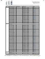


Parameter
Name / value range / [default setting]
Info
Bit 1 Digital output 1
0 ≡ LOW level, 1 ≡ HIGH level.
Bit 2 Digital output 2
Bit 3 Reserved
-
Bit 4
Bit 5
Bit 6
Bit 7
Bit 8
Bit 9
Bit 10 Charge Relay
Bit 11 Reserved
-
Bit 12
Bit 13
Bit 14
Bit 15
0x603F
(PAR 150)
Error code
(Active error)
•
Read only
Error message
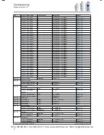
5.3.4
Network diagnostics
The following parameters show some general information with regard to the network option
available and the network.
Further fieldbus-specific diagnostic parameters are described in the following subchapters.
Parameter
Name / value range / [default setting]
Info
0x282B:005
(PAR 125/005)
Inverter diagnostics: Most recently used control
register
(Inverter diag.: Netw. contr.reg.)
•
Read only
Display of the network register for the control that was accessed last
(e. g. 0x6040 or 0x400B:1).
•
Format: 0xiiiiss00 (iiii = hexadecimal index, ss = hexadecimal subindex)
•
The lowest byte is always 0x00.
0x282B:006
(PAR 125/006)
Inverter diagnostics: Most recently used setpoint
register
(Inverter diag.: Netw. setp.reg.)
•
Read only
Display of the network register for setpoint selection that was accessed
last (e. g. 0x6042 or 0x400B:3).
•
Format: 0xiiiiss00 (iiii = hexadecimal index, ss = hexadecimal subindex)
•
The lowest byte is always 0x00.
0x400B:006
(PAR 592/006)
Predefined process input data: Network speed
setpoint
(Legacy NetWordIN: Netw. speed setp.)
-599.0 ... [0.0] ... 599.0 Hz
Display of the setpoint received via network for speed mode.
0x400B:007
(PAR 592/007)
Predefined process input data: Network process
controller setpoint
(Legacy NetWordIN: Netw. PID setp.)
-300.00 ... [0.00] ... 300.00 PUnit
Display of the setpoint received via network for process controller mode.
0x400B:008
(PAR 592/008)
Predefined process input data: Network torque
setpoint
(Legacy NetWordIN: Netw. torque setp.)
-32768 ... [0] ... 32767 Nm
Display of the setpoint received via network for torque mode.
0x231F:001
(PAR 500/001)
Module ID: Active module ID
(Module ID: Active module ID)
•
Read only
•
Default setting depending on the size.
Display of the network options currently configured in the inverter.
•
When the "Load Lenze settings" device command
0x2022:001
(PAR 700/001)
or "Accept new inverter hardware"
0x2022:027
(PAR 700/027)
is executed, the module ID is stored in the memory
module.
•
With the help of this module ID, the keypad only shows the communi-
cation parameters relevant to the respective network.
0 No network
67 CANopen
80 PROFIBUS
87 Modbus
Diagnostics and fault elimination
Diagnostics
Network diagnostics
53
Phone: 800.894.0412 - Fax: 888.723.4773 - Web: www.actechdrives.com - Email: [email protected]