Ch.2 Unpacking and Installation
< 80 >
DRYPRO Vstage MODEL 793 Installation Manual Ver.1.00 2004.11
14X11"
14X14"
14X17"
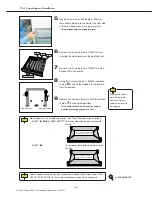
Do not remove.
6
Remove the 2 screws (Sems
2
M4X15) from
securing the side stoppers at the front and rear.
9
Replace the 2 screws (Sems
2
M4X8) removed
in step-
7
in the original positions.
- This will block the screw holes at the original
position preventing exposure to light.
7
Remove the 2 screws (Sems
2
M4X10) at the
desired film size position.
8
Using the 2 screws (Sems
2
M4X15) removed
in step-
6
, set the side stoppers in the desired
film size position.
All removed screws
must be replaced.
Failure to replace
screws may result in
film fogging.
6
7
9
8
Original Position
New Position
5
Insert a driver with a shaft length of 90mm or
more shown below into the hole on the right side
of the main body press the supply tray latch.
- This will disengage the supply tray lock.
After changing the supply tray film size position, size and type settings under "FILM
SETUP" (TRAY SETUP) in the service maintenance mode must be changed.
p.102 FILM SETUP
Side stoppers have a smooth and a rough side. These should be used as follows:
14X11" (B, DR-B), 14X14", 14X17"
: The rough side should make contact with
the film.
14X11" (M)
: The smooth side should make contact with
the film.
Fix the stoppers so that the rough
side makes contact with the film.
Fix the Stoppers so that the
smooth side makes contact with
the film.
Содержание DRYPRO793
Страница 4: ......
Страница 34: ...Ch 1 Pre installation Information 30 DRYPRO Vstage MODEL 793 Installation Manual Ver 1 00 2004 11...
Страница 88: ...Ch 2 Unpacking and Installation 84 DRYPRO Vstage MODEL 793 Installation Manual Ver 1 00 2004 11...
Страница 140: ...Ch 3 Setup 136 DRYPRO Vstage MODEL 793 Installation Manual Ver 1 00 2004 11...
Страница 198: ...Ch 6 Web Maintenance Mode 194 DRYPRO Vstage MODEL 793 Installation Manual Ver 1 00 2004 11...

