Ch.2 Unpacking and Installation
< 70 >
DRYPRO Vstage MODEL 793 Installation Manual Ver.1.00 2004.11
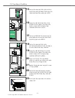
Unit Drive Board
Power IF Board
UJJ4
UJP4
CN13
PCN13
Sorter Power Assy
Relay Box Cover
18
Connect the connector (UJJ4) on the
mechanical control board of sorter main body to
the cable (Sorter Power Assy) connector.
22
Connect the connector (CN13) on the power
interface board in the DRYPRO 793 main body
and the cable (Sorter Power Assy) connector
(PCN13).
19
Secure the cable (Sorter Power Assy) to the
DRYPRO 793 main body in the clamps at the
locations shown at left (rectangles shown
superimposed the cable (yellow)).
20
Loosen the 2 screws (TP screws M4X8),
remove the relay box cover and pass the cable
(Sorter Power Assy) through the box.
21
Replace the relay box cover using the 2 screws
(TP screws M4X8).
Unit Drive Board
Mech Ctl Board
Sorter Signal Assy
UJJ8
UJP8
CN16
MCN16
15
Connect the connector (UJJ8) on the unit drive
board of the sorter main body and the accessory
cable (Sorter Signal Assy) connector (UJP8).
17
Connect the DRYPRO 793 mechanical control
board connector (CN16) and the cable (Sorter
Signal Assy) connector (MCN16).
16
Secure the cable (Sorter Signal Assy) to the
DRYPRO 793 main body in the clamps at the
locations shown at left (rectangles shown
superimposed the cable (.yellow)).
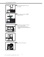
Sorter Front Cover
23
Set the sorter front cover down in the location
shown at left.
Содержание DRYPRO793
Страница 4: ......
Страница 34: ...Ch 1 Pre installation Information 30 DRYPRO Vstage MODEL 793 Installation Manual Ver 1 00 2004 11...
Страница 88: ...Ch 2 Unpacking and Installation 84 DRYPRO Vstage MODEL 793 Installation Manual Ver 1 00 2004 11...
Страница 140: ...Ch 3 Setup 136 DRYPRO Vstage MODEL 793 Installation Manual Ver 1 00 2004 11...
Страница 198: ...Ch 6 Web Maintenance Mode 194 DRYPRO Vstage MODEL 793 Installation Manual Ver 1 00 2004 11...

