Ch.2 Unpacking and Installation
< 75 >
DRYPRO Vstage MODEL 793 Installation Manual Ver.1.00 2004.11
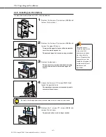
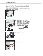
2.4.12 Installing 1GB Print Memory (Option)
In configurations including the 1GB print memory option, the memory should be installing the
supply tray.
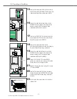
1
Remove the 2 screws (TP screws M4X8) and
remove the relay box located at the bottom right
of the back of the main body.
Relay Box Cover
2
Disconnect the connector (SJP2) at the left edge
of the control box.
SJP2
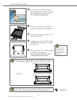
3
Remove the 4 screws (TP screws M4X6) and
remove the control box cover.
Installation or removal of the memory should be carried out only after ensuring that
the power cable is disconnected from the main body. Attempting installation with the
power cable connected may result in electric shock causing injury and/or damage to
the equipment.
Installation or removal of the memory should be carried out only after ensuring that
neither LAN nor serial cables are connected. Attempting installation with LAN and/or
serial cables connected may result in damage to cables or connectors.
Since the following procedure involves handling circuit boards, wristbands must be
worn.
Содержание DRYPRO793
Страница 4: ......
Страница 34: ...Ch 1 Pre installation Information 30 DRYPRO Vstage MODEL 793 Installation Manual Ver 1 00 2004 11...
Страница 88: ...Ch 2 Unpacking and Installation 84 DRYPRO Vstage MODEL 793 Installation Manual Ver 1 00 2004 11...
Страница 140: ...Ch 3 Setup 136 DRYPRO Vstage MODEL 793 Installation Manual Ver 1 00 2004 11...
Страница 198: ...Ch 6 Web Maintenance Mode 194 DRYPRO Vstage MODEL 793 Installation Manual Ver 1 00 2004 11...

