Print Engine Board
Main CPU Board
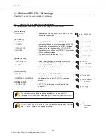
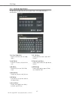
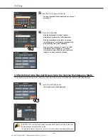
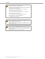
Ch.2 Unpacking and Installation
< 76 >
DRYPRO Vstage MODEL 793 Installation Manual Ver.1.00 2004.11
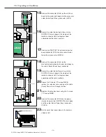
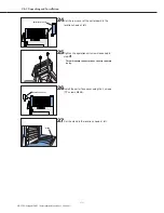
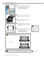
Do not touch the edges (gold) of the memory module.
There is a notch at one point on the edge of the module: when installing, ensure that
the module is set so that the notch on the module and the socket face the same
direction.
6
Write the date and details (1Gbyte) of the
installed memory module in the space provided
on the label affixed to the mechanical control
box cover.
7
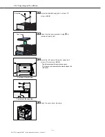
Secure the control box cover using the 4 screws
(TP screws M4X6).
5
Install the 1GB memory module in the DIMM
socket on the main print engine board.
4
Open the lock levers at both edges of the DIMM
socket on the print engine board to both sides
and remove the 512MB memory module.
Opening the lock levers
too forcefully may result
in the memory module
being dropped.
Care must be taken to
ensure that the module
is not dropped by, for
example, lightly holding
the module in place
while disengaging the
lever locks.
Ensure that the removed 512MB memory module is handed to the user.
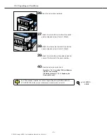
When securing the control box cover, be careful that the main cooling fan cable
does become trapped between the box and the cover.
Also ensure that the control box gasket is not removed.
メインCPUボードにも
プリントエンジンボード
と同様のメモリーが付い
ています。
メインCPUボードのメ
モリーは取り外さないで
ください。
Содержание DRYPRO793
Страница 4: ......
Страница 34: ...Ch 1 Pre installation Information 30 DRYPRO Vstage MODEL 793 Installation Manual Ver 1 00 2004 11...
Страница 88: ...Ch 2 Unpacking and Installation 84 DRYPRO Vstage MODEL 793 Installation Manual Ver 1 00 2004 11...
Страница 140: ...Ch 3 Setup 136 DRYPRO Vstage MODEL 793 Installation Manual Ver 1 00 2004 11...
Страница 198: ...Ch 6 Web Maintenance Mode 194 DRYPRO Vstage MODEL 793 Installation Manual Ver 1 00 2004 11...


