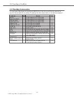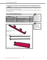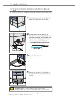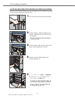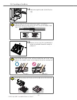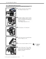
To set the protection
hardware back in place
in the event that the
unit is to be moved,
remove the pickup unit
before replacing the
protection hardware.
Since protection
hardware may be used
again, they must be
placed in the bag
provided after removal
and returned to the
manufacturer.
Ch.2 Unpacking and Installation
< 44 >
DRYPRO Vstage MODEL 793 Installation Manual Ver.1.00 2004.11
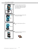
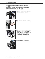
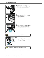
8
Return supply tray 1 to its position in the main
body.
- Removing the screw and pulling the protection
hardware forward a little will release the section
securing the rear of the pickup unit enabling
removal of the component.
- The procedure for installation of supply tray 2&3
(option) is described on the following page.
If supply tray 2 &3 is not to be installed, proceed to
installing covers (1) (2.4.7).
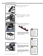
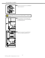
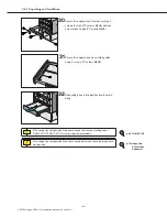
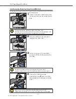
7
Remove the screw (TP screw M4X8) securing
the protection hardware securing the pick up
unit and remove the component.
- Removing the screw and pulling the protection
hardware forward a little will release the section
securing the rear of the pick up unit enabling
removal of the component.
View of underside of pick up unit with
protection hardware in place
Front side
Rear side
When removing the
protection hardware
securing the pick up
unit, be careful not to
cause damage with the
outer edges of the
component
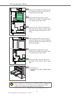
6
正面のネジ2本(TPネジM4x8)を外し、両端のネ
ジ各1本(TPネジM4x8)を緩めて
, and remove the
supply tray 1 front cover.
Protection hardware securing
the pick up unit
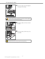
5
Loosen the 2 screws (TP screws M4X8) and
remove the supply tray 1 cover.
Tray Cover
Содержание DRYPRO793
Страница 4: ......
Страница 34: ...Ch 1 Pre installation Information 30 DRYPRO Vstage MODEL 793 Installation Manual Ver 1 00 2004 11...
Страница 88: ...Ch 2 Unpacking and Installation 84 DRYPRO Vstage MODEL 793 Installation Manual Ver 1 00 2004 11...
Страница 140: ...Ch 3 Setup 136 DRYPRO Vstage MODEL 793 Installation Manual Ver 1 00 2004 11...
Страница 198: ...Ch 6 Web Maintenance Mode 194 DRYPRO Vstage MODEL 793 Installation Manual Ver 1 00 2004 11...


