


4
CP - Parameter
Operation
4
3
19
KEB COMBIVERT F5-M / S
Name: Basis
17.05.04
Section
Page
Date
©
KEB Antriebstechnik, 2003
All Rights reserved
Chapter
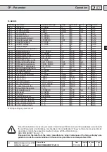
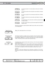
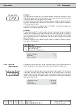
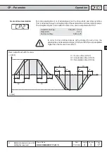
Switching frequency
The switching frequency with which the power modules are clocked can be changed
depending on the application. The employed power stage determines the maximum
switching frequency as well as the factory setting (see manual: part2). Refer to following
list to learn about influences and effects of the switching frequency.
low switching frequency
Åless inverter heating
Åless discharge current
Åless switching losses
Åless radio interferences
Åimproved concentricity with low speed
(only controlled!)
high switching frequency
Åless noise development
Åimproved sine-wave simulation
Åless motor losses
Åimproved controller characteristics
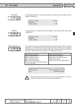
Adjustment range (dep. on power circuit): 2 / 4 / 8 / 12 / 16 kHz
Factory setting:
depending on power circuit
Note:
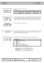
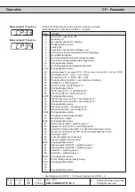
ENTER-Parameter
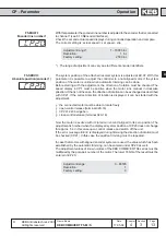
KI speed
The integral factor of the speed controller is adjusted in these parameters (see chapter
7.2 ÑStart-upì).
Adjustment range:
0...32767
Resolution:
1
Factory setting:
100
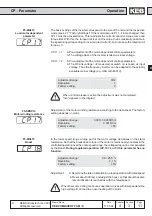
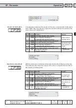
KP speed
The proportional factor of the speed controller is adjusted in these parameters (see
chapter 7.2 ÑStart-upì).
Adjustment range:
0...32767
Resolution:
1
Factory setting:
300
At switching frequencies above 4 kHz pay absolute attention to the max.
motor line length in the technical data of the chapter 2.1.