


6
Functional Description
Analog In- and Outputs
6
2
11
KEB COMBIVERT F5
Name: Basis
Chapter Section
Page
Date
©
KEB Antriebstechnik, 2002
All rights reserved
04.05.04
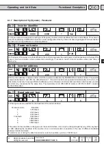
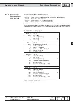
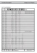
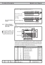
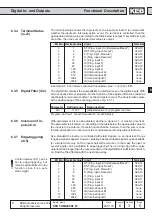
6.2.12 Analog Output /
Functions
(An.31/An.36/
An.41)
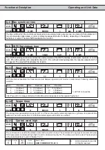
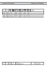
These parameters define the function which controls the respective output. Following
adjustments are possible:
An.xx
Function
Scaling factor 0...100 %
0
absolute actual value
0...100 Hz/3000 min
-1
2)
1
absolute set value
0...100 Hz/3000 min
-1
2)
2
actual value ru.7
0...±100 Hz/±3000 min
-1
2)
3
set value ru.1
0...±100 Hz/±3000 min
-1
2)
4
output voltage ru.20
0...500 V
5
DC voltage ru.18
0...1000 V
6
apparent current ru.15
0...2 è I
rated
1)
7
active current ru.17
0...2 è ±I
rated
1)
8
digital An.32/An.37/An.42
0...100 %
9
external PID output ru.52
0...±100 %
10
absolute ext. PID output ru.52
0...100 %
11
absolute active current ru.17
0...2 è I
rated
1)
12
power mod. temperature ru.38
0...100
∞
C
13
Motor temperature ru.46
0...100
∞
C
14
actual torque (F5-M/S)
0...± 3 ï rated torque
15
absolute actual torque (F5-M/S)
0...3 ï rated torque
16
set torque (F5-M/S)
0...± 3 ï rated torque
17
absolute set torque (F5-M/S)
0...3 ï rated torque
18
system deviation/speed controller
0...±100 Hz/±3000 min
-1
2)
19
speed reference variable ru.2
0...±100 Hz/±3000 min
-1
2)
20
absolute speed reference variable ru.2
0...100 Hz/1000 min
-1
2)
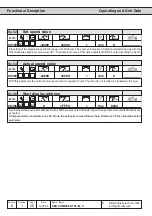
1)
dependent of inverter rated current (In.1)
2)
dependent of ud.2
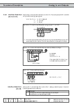
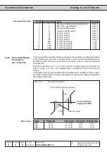
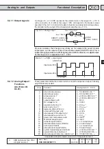
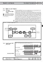
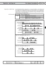
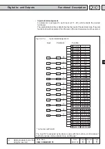
6.2.11 Output signals
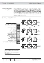
A voltage of 0...±11,5 VDC represents the selected size in the range of 0...±115 %
with a resolution of ±10 Bit at the output. 100% correspond to the bracket values
specified in Fig. 6.2.10. In order to be able to balance load-dependent voltage drops,
the limitation at the output of the characteristic amplifiers is ±115 %.
AGND
(X2A.8 / X2A.9)
+
-
ANOUT1 (X2A.5) /
ANOUT2 (X2A.6)
U
out
= 0...±10V
R
B
I
max
= 5mA
R
i
< 100
W
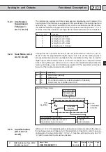
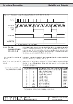
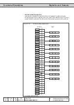
Process variables, that change only slowly, as for example the power module
temperature, can be output over two virtual analog outputs (ANOUT3 and 4). This is
realised through generation of a PWM-signal (pulse-width-modulation) on a digital output.
At that the period T is adjustable from 1...240 s.
T= An.46/52
t
Bild 6.2.11.a PWM - output signal
ANOUT 3/4
Input value 50 %
Input value 25 %
Fig. 6.2.11 Analog output