


6
11
KEB COMBIVERT F5-M / S
6
Name: Basis
06.05.04
Chapter
Section
Page
Date
©
KEB Antriebstechnik, 2002
All Rights reserved
Functional Desription
Positioning and Synchronous Control
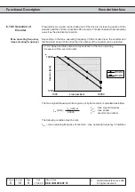
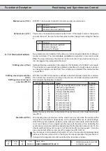
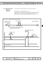
6.11.5 Reference Point
Approach
Following conditions must be met for a reference point approach:
ï connect the limit switches to the inputs clockwise run (F) and counter-
clockwise run (R)
ï program an input as reference point approach and connect it (it can serve at
the time as limit switch)
ï determine an input for starting the reference point approach
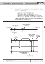
The reference point approach is started with the rising edge at the input Ñstart
reference point approachì. The reference point approach starts with the reference
speed adjusted in PS.21. The preferred direction is determined by the sign.
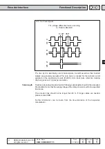
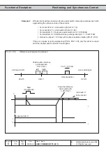
The drive reverses when it runs onto a limit switch. On reaching the reference point
switch the initiator is cleared with 25 % of the reference speed. Whether the stopping
point is on the left or the right of the reference point switch is defined by PS.14 Bit
3. If PS.14 Bit 2 and Bit are activated, the drive trips to error E.EnC, if no valid zero
impulse has been detected. If Bit 4 is deactivated, the drive turns 2 revolutions
back and forth. If still no valid zero signal is being detected, the error EnC is
triggered, otherwise the drive keeps turning until zero position. If the drive finds no
zero position, the error message E.EnC can be generated with Bit 4.
After completing the reference point approach the actual position is overwritten
with the reference point PS.17 and the switching condition Ñreference point approach
completedì (do.0...do.7 value Ñ29ì) is set.
The ramps must be adjusted in such a way that the drive comes to a safe stop at
the limit switches or can reverse.
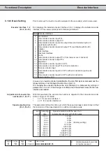
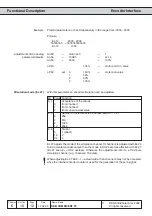
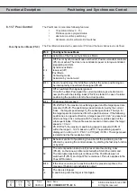
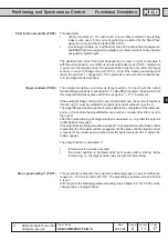
Mode of position reference
(PS.14)
PS.14
Reference point drive mode
Bit 0...1 Reference point drive mode
0
No reference point drive
1
The reference point drive can be started only via a digital input. The
input is defined with PS.19.
2
The reference point drive is automatically executed at the first îStart
Posiì-command.
3
The position value is stored. If it can be ensured that the drive does
not rotate anymore after switching off the inverter, no new reference
point drive is necessary. The drive starts with the stored position
value.
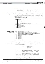
Bit 2
Stop at zero signal; in this bit it is adjusted, whether the drive keeps
on running to the zero point after driving free of the reference point
switch.
0
The drive stops directly after driving free of the reference point switch.
4
The drive keeps on running to the zero point after driving free of the
reference point switch. If no zero signal is detected, an error message
is output dependent on bit 4.
Bit 3
Stop point; this setting is only taken into account if the reference point
switch does not serve at the same time as limit switch. The ramp
times must be selected so that the drive can reverse on the reference
point switch.
0
Stop on the right side of the reference point switch.
8
Stop on the left side of the reference point switch.
Bit 4
Error, if no zero signal is detected.