


3
2
1
3
KEB COMBIVERT F5
Name: Basis
04.05.04
2
©
KEB Antriebstechnik, 2002
All Rights reserved
Product Description
Summary
Section
Page
Date
Chapter
L1
L2
(L3)
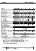
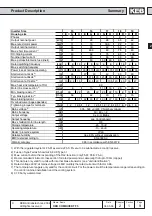
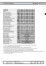
2.1.1
Features of KEB
COMBIVERT
2.1
Product Description
KEB
COMBIVERT
8 parameter sets
14 parameter groups
Prog. Operator menu
2 prog. relay outputs
8 prog. digital inputs
2 prog. digital output
2 prog. analog output
2 prog. analog inputs
Hardware current limit
Autoboost
Slip compensation
DC-braking
Jogging-function (prog.)
Speed search
Power-Off function
HSP5 interface
Energy saving function
PID-controller
Protective equipment
Electr. motor protection
Prog. filter for analog and digital inputs
Software In-/Outputs
Adjustable balancing of the ramps
Hour meter
2.1.2
Function
Principle
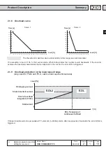
The power circuit of a frequency inverter consists basically of a mains rectifier, the
DC-link and an inverter at the output. The mains rectifier consists of an uncontrolled
single or three-phase bridge connection, the single-phase design is restricted to small
powers. It converts the AC-voltage of the mains into a DC-voltage, which is smoothed
by the DC-link capacitor, thus in the ideal case (inverter unloaded) the DC-link is
charged with a voltage of U
ZK
=
√
2
.
U
N.
Since during the charging of the DC-link capacitor very high currents flow for a short
time which would lead to the tripping of the input fuses or even to the destruction of
the mains rectifier, the charging current must be limited to a permissible level. This is
achieved by using an inrush current limiting resistor in series to the capacitor. After
the charging of the capacitor is completed the limiting resistor is bridged, for example,
by a relay and is therefore only active at the switch-on of the inverter.
As the smoothing of the DC-link voltage requires a large capacity, the capacitor still
has a high voltage for some time after the disconnection of the inverter from the
mains.
The actual task of the frequency inverter, to produce an output voltage variable in
frequency and amplitude for the control of the three-phase AC motor, is taken over by
the converter at the output. It makes available a 3-phase output voltage according to
the principle of the pulse-width modulation, which generates a sinusoidal current at
the three-phase asynchronous motor
Picture 2.1.2
Block diagram of an inverter power circuit
2.
Overview
Encoder interface
=
~
=
~
U
N
R
C
W
U
V
U
ZK
Mains rectifier
Motor
Converter
DC-link