


6
Functional Description
Analog In- and Outputs
6
2
7
KEB COMBIVERT F5
Name: Basis
Chapter Section
Page
Date
©
KEB Antriebstechnik, 2002
All rights reserved
04.05.04
100%
100%
-100%
-100%
100%
100%
-100%
-100%
An.6
50%
100%
100%
-100%
-100%
An.5
1.
2.
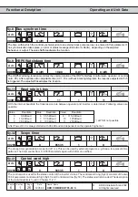
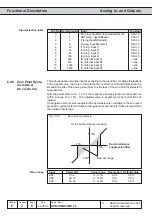
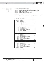
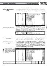
6.2.7
Amplifier of the
Input Characterstic
(An.5...7; An.15...17;
An.25...27)
With these parameters the input signals can be adapted in X and Y direction as well
as in the rise to the requirements. In the case of factory setting no zero point offset is
adjusted, the rise (gain) is 1, i.e. the input value corresponds to the output value of
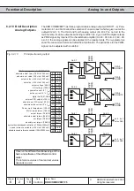
this step (see Fig. 6.2.7.a) The output value is calculated according to following formula:
Out = Amplification ï ( In - Offset X) + Offset Y
Input value (In)
Output value (Out)
Fig. 6.2.7.a
Factory setting: no Offset, Gain 1
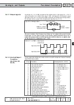
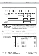
By means of some examples, we want to show the possibilities of this function.
According to Fig. 6.2.7.b
1. adjustment of the X-Offset for input AN1 to 50 (%)
2. adjustment of the amplificaiton to 2
Fig. 6.2.7.b
X-Offset (An.6)=50%; amplification (An.5)=2.00
With these settings the entire speed
range can be driven with 0...10 V
via input AN1.
(rotation direction = ±analog)
0%
In corresponds to-100% Out
50% In corresponds to 0% Out
100% In corresponds to 100% Out
Input
AN1
AN2
AN3
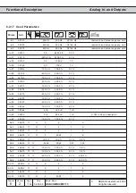
Value range
Resolution Default value
Amplification An.5 An.15 An.25
-20,00...20,00
0,01
1,00
Offset X
An.6 An.16 An.26 -100,0%...100,0%
0,1%
0,0%
Offset Y
An.7 An.17 An.27 -100,0%...100,0%
0,1%
0,0%