6
4
KEB COMBIVERT F5-M / S
2
Name: Basis
12.05.04
Chapter
Section
Page
Date
©
KEB Antriebstechnik, 2002All Rights reserved
Functional Desription
Setpoint- and Ramp Adjustment
Страница 1: ...APPLICATION MANUAL 05 2004 Part No 00 F5 MEA K270 Charge 40 EURO KEB COMBIVERT F5 MULTI SERVO 2 7...
Страница 2: ...1 1 Name Basis KEB COMBIVERT F5 M S 2 18 05 04 Introduction General KEB Antriebstechnik 2002 All Rights reserved Chapter Section Page Date...
Страница 3: ...mprises addresses value ranges and references with regard to the functions for which they are used To make the programming easier all inverter functions and the parameters belonging to it are comprise...
Страница 4: ...Introduction 1 1 Name Basis KEB COMBIVERT F5 M S 4 18 05 04 KEB Antriebstechnik 2002 All Rights reserved Chapter Section Page Date...
Страница 5: ...Parameter 6 Functions 7 Start up 8 Special Operation 9 Error Assistance 10 Project Planning 11 Networks 12 Annex 1 1 5 18 05 04 KEB COMBIVERT F5 M S Name Basis KEB Antriebstechnik 2002 All Rights res...
Страница 6: ...1 1 Name Basis KEB COMBIVERT F5 M S 6 18 05 04 Introduction General KEB Antriebstechnik 2002 All Rights reserved Chapter Section Page Date...
Страница 7: ...the lower speed range 2 1 13 3 Hardware 3 1 3 3 1 Control Units 3 1 3 3 1 1 Survey 3 1 3 3 1 2 Housing Size D E 3 1 4 3 1 3 Housing Size G 3 1 4 3 1 4 Terminal strip X2A 3 1 5 3 1 5 Connection of the...
Страница 8: ...ontrol 5 1 4 5 1 3 F5 SERVO Control 5 1 4 5 1 4 F5 A SERVO Control 5 1 4 5 1 5 Parameter Listing 5 1 5 6 Functional Description 6 1 3 6 1 Operating and Unit Data 6 1 3 6 1 1 Summary of ru Parameter 6...
Страница 9: ...puts 6 3 11 6 3 13 Output Signals 6 3 12 6 3 14 Output filter do 43 do 44 6 3 12 6 3 15 Switching Conditions do 0 do 7 6 3 13 6 3 16 Inverting of Switching Conditions for Flags do 8 do 15 6 3 16 6 3 1...
Страница 10: ...sed Parameters 6 6 16 6 7 Protective Functions 6 7 3 6 7 1 Ramp Stop and Hardware Current Limit 6 7 3 6 7 2 Current Limit Constant Run Stall Function 6 7 5 6 7 3 Automatic Restart and Speed Search 6 7...
Страница 11: ...11 1 Synchronous Control 6 11 3 6 11 2 Slave Correction 6 11 4 6 11 3 Position Controller 6 11 5 6 11 4 Position Display 6 11 5 6 11 5 Reference Point Approach 6 11 6 6 11 6 Reference Point Approach E...
Страница 12: ...Resistors 10 1 4 10 1 3 Cable and Fuses 10 1 6 11 Networks 11 1 3 11 1 Network Components 11 1 3 11 1 1 Available Hardware 11 1 3 11 1 2 RS232 Cable PC Operator 00 58 025 001D 11 1 3 11 1 3 HSP5 Cabl...
Страница 13: ...ho does not know this demand from purchasing departments production or service We have taken this request very seriously and developed a series with open programming which can be adapted to the differ...
Страница 14: ...Introduction 1 1 Name Basis KEB COMBIVERT F5 M S 14 18 05 04 KEB Antriebstechnik 2002 All Rights reserved Chapter Section Page Date...
Страница 15: ...2 1 1 KEB COMBIVERT F5 Name Basis 04 05 04 KEB Antriebstechnik 2002 All Rights reserved Section Page Date Chapter 2 1 1 Features of KEB COMBIVERT 3 2 1 2 Function Principle 3 2 1 3 Application as dire...
Страница 16: ...2 1 KEB COMBIVERT F5 2 Name Basis 04 05 04 KEB Antriebstechnik 2002 All Rights reserved Product Description Summary Chapter Section Page Date...
Страница 17: ...citor thus in the ideal case inverter unloaded the DC link is charged with a voltage of UZK 2 UN Since during the charging of the DC link capacitor very high currents flow for a short time which would...
Страница 18: ...usively for the stepless speed control of three phase AC motors The unit has been developed subject to the relevant safety standards and is manufactured with the highest demands on quality Condition f...
Страница 19: ...400 480 3 16 kHz 125 150 8 2 kHz 180 216 D 4 kHz 200 240 I 8 kHz 400 480 4 2 kHz 150 180 9 4 kHz 180 216 E 8 kHz 200 240 K 16 kHz 400 480 at Servos motor speed 1 1500 rpm 2 2000 rpm 3 3000 rpm 4 4000...
Страница 20: ...permissible mains fuse inert Rated switching frequency Max switching frequency Power loss at nominal operating Power loss at rated operation2 Stall current at 4kHz 3 Stall current at 8kHz 3 Stall cur...
Страница 21: ...current at 16kHz 2 Max heat sink temperature TOH Motor line cross section 3 Min braking resistor 4 Typ braking resistor 4 Max braking current Overload curve page appendex Tightening torque for termin...
Страница 22: ...Motor line cross section 3 Min braking resistor 4 Typ braking resistor 4 Max braking current Overload curve page appendex Tightening torque for terminals Mains voltage 5 Mains frequency Output voltage...
Страница 23: ...inert Rated switching frequency Max switching frequency Power loss at nominal operating Stall current at 4kHz 2 Stall current at 8kHz 2 Stall current at 16kHz 2 Max heat sink temperature TOH Motor lin...
Страница 24: ...resistor 4 Typ braking resistor 4 Max braking current Overload curve page appendex Tightening torque for terminals Mains voltage 5 Mains frequency Output voltage Output frequency Max shielded motor li...
Страница 25: ...rque for terminals Mains voltage 5 Mains frequency Output voltage Output frequency Max shielded motor line length Storage temperature Operating temperature Model protective system Relative humidity EM...
Страница 26: ...curve 2 Tightening torque for terminals Nm 25 30 Mains voltage 6 V 305 500 0 Mains frequency Hz 50 60 2 Output voltage V 3 x 0 U mains Output frequency Hz see control card Max shielded motor line leng...
Страница 27: ...ounter counts backwards If the counter achieves the overload characteristic that corresponds to the inverter the error E OL is triggered Curve 1 30 60 90 120 150 180 210 240 270 300 0 105 110 115 120...
Страница 28: ...2 1 KEB COMBIVERT F5 14 Name Basis 04 05 04 KEB Antriebstechnik 2002 All Rights reserved Product Description Summary Chapter Section Page Date...
Страница 29: ...T F5 M S Name Basis 18 05 04 Section Page Date KEB Antriebstechnik 2002 All Rights reserved Chapter 3 1 1 Survey 3 3 1 2 Housing Size D E 4 3 1 3 Housing Size G 4 3 1 4 Terminal strip X2A 5 3 1 5 Conn...
Страница 30: ...Hardware Control Cards 3 1 KEB COMBIVERT F5 M S 2 Name Basis 18 05 04 Chapter Section Page Date KEB Antriebstechnik 2002 All Rights reserved...
Страница 31: ...grammable 8 8 Internal inputs 4 4 External supply of the control card X X Encoder interface X X Scan time of the in and outputs 1 ms 1 ms Outputs Analog outputs 2 2 Digital outputs 2 2 Relay outputs 2...
Страница 32: ...t f o r P C S T O P S P E E D F U N C F R S T A R T E N T E R C O M B I V E R T OptionalOperator with 9 pole Sub D Socket ParameterInterface OptionalOperator with 9 pole Sub D Socket ParameterInterfa...
Страница 33: ...r Input 2 I2 inputs see chapter 6 3 12 Progr Input 3 I3 All digital inputs are free programmable 13 Progr Input 4 I4 The control release is firmly linked with the input ST but can be 14 Progr InputFor...
Страница 34: ...Externalanalog set point setting X2A 1 2 3 4 5 6 7 8 9 R 3 10 kW PE 3 1 5 Connection of the control 3 1 6 Digital inputs In order to prevent a malfunction caused by interference voltage supply on the...
Страница 35: ...se of inductive load on the relay outputs a protective wiring must be provided e g free wheeling diode The supply of the control circuit through an external voltage source keeps the control in operati...
Страница 36: ...3 1 11 Analog Outputs 3 1 12 Voltage Output The voltage output serves for the setting of the digital inputs as well as for the supply of external control elements Do no exceed the maximum output curr...
Страница 37: ...1 Networks 12 Annex KEB COMBIVERT F5 Name Basis 4 1 1 04 05 04 KEB Antriebstechnik 2002 All Rights reserved Section Page Date Chapter 4 1 1 Parameters Parameter Groups Parameter Sets 3 4 1 2 Selection...
Страница 38: ...4 1 KEB COMBIVERT F5 2 Name Basis 04 05 04 Operation Fundamentals KEB Antriebstechnik 2002 All Rights reserved Chapter Section Page Date...
Страница 39: ...the exception of the control release no termi nal wiring is needed What are parameters parameter groups and parameter sets Parameters are values changeable by the operator in a program which have an i...
Страница 40: ...r values can be changed only when the parameter set is not adjusted to Active parameter set A see 4 1 6 For some parameters it is not sensible that the selected values become active immediately For th...
Страница 41: ...The resetting of the error message with ENTER is no error reset i e the error status in the inverter is not reset Thus it is possible to correct adjustments before the error reset An error reset is on...
Страница 42: ...4 1 KEB COMBIVERT F5 6 Name Basis 04 05 04 Operation Fundamentals KEB Antriebstechnik 2002 All Rights reserved Chapter Section Page Date...
Страница 43: ...Operation 5 Parameter 6 Functions 7 Start up 8 Special Operation 9 Error Assistance 10 Project Planning 11 Networks 12 Annex 1 4 2 1 KEB COMBIVERT F5 Name Basis 04 05 04 KEB Antriebstechnik 2002 All...
Страница 44: ...4 2 KEB COMBIVERT F5 2 Name Basis 04 05 04 KEB Antriebstechnik 2002 All Rights reserved Operation Password Structure Chapter Section Page Date...
Страница 45: ...mode is active The parameter value of the above parameters shows the actual password level Following indications are possible CP read only CP on CP Service Application Drive Mode 4 2 1 Password Levels...
Страница 46: ...ve password level Passwords Password level DRIVE Mode START ENTER F R FUNCT SPEED START START FUNCT SPEED To finish the Drive Mode press ENTER FUNCT key for approx 3 sec see chapter 4 4 Example 1 Swit...
Страница 47: ...eration 9 Error Assistance 10 Project Planning 11 Networks 12 Annex 4 3 1 KEB COMBIVERT F5 M S Name Basis 17 05 04 Section Page Date KEB Antriebstechnik 2003 All Rights reserved Chapter 4 3 1 Operatio...
Страница 48: ...CP Parameter Operation 4 3 KEB COMBIVERT F5 M S 2 Name Basis 17 05 04 Chapter Section Page Date KEB Antriebstechnik 2003 All Rights reserved...
Страница 49: ...put they can be defined by the user The following Parameters are preset at delivery Advantages from it operator friendly for the customer critical parameters are protected against maloperation low doc...
Страница 50: ...0 0 1 LTK Hz dr 5 CP 13 DASM rated current 0 0 710 0 1 LTK A dr 0 CP 14 DASM rated voltage 120 500 1 LTK V dr 2 CP 15 DASM rated cos phi 0 50 1 00 0 01 LTK dr 4 CP 16 DASMratedpower 0 35 400 00 0 01...
Страница 51: ...4 5 1 0 cs 0 CP 11 DSM rated torque 0 1 6553 5 0 1 LTK Nm dr 27 CP 12 DSM rated speed 0 32000 1 LTK rpm dr 24 CP 13 DSM rated frequency 0 0 1600 0 0 1 LTK Hz dr 25 CP 14 DSM rated current 0 0 710 0 0...
Страница 52: ...nd their meanings are noOperation controlreleasenotbridged modulationswitchedoff output voltage 0 V drive is not controlled Low Speed no rotation preset modulation switched off output voltage 0 V driv...
Страница 53: ...Apparentcurrent Peakvalue Actualtorque CP 5 makes it possible to recognize the max apparent current For that the highest value of CP 4 is stored in CP 5 The peak value memory can be cleared by pressin...
Страница 54: ...h off of the inverter also clears the memory Display of the actual output voltage in volt Speed control Configuration With this parameter the basic setting of the speed controller is determined Adjust...
Страница 55: ...ing LTK F5 MULTI DASMratedspeed Adjustment of rated motor speed according to the name plate The factory setting depends on the unit size see 4 3 7 Factory Settings Adjustmentrange 0 64000rpm Resolutio...
Страница 56: ...and the connection Y The factory setting depends on the unit size see 4 3 7 Factory Settings Adjustmentrange 120 500 V Resolution 1 V Factory setting LTK F5 SERVO Ratedmotorcurrent Adjustment of the r...
Страница 57: ...available mains voltage e g USA with 460 V Adjustmentrange 0 2 Resolution 1 Factory setting 0 When control release is active the adjustment was not completed nco appears in the display F5 SERVO Motorw...
Страница 58: ...z Factory setting 50 Hz The basic settings of the inverter correspond to the size of the unit and the respective motor see 4 3 7 Factory Settings If the motor data in CP 11 18 are changed then CP 19 m...
Страница 59: ...ve when the motor runs manual in clockwise direction If that is not the case the direction of rotation can be exchanged as described with CP 21 If the correct direction of rotation is displayed it can...
Страница 60: ...e shaft F5 SERVO The speed display at CP 1 must be positive when the engine runs manual in clockwise direction The signals SIN and SIN of the resolver have to be changed if the sign is wrong Please en...
Страница 61: ...should accelerate from 300 rpm to 800 rpm in 1 s n 800 rpm 300 rpm 500 rpm t 1 s t 1 s CP 25 x 1000 rpm x 1000 rpm 2 s n 500rpm t s CP 25 n rpm 1000 800 300 0 0 5 1 1 5 2 t n Step speed 1 and 2 Input...
Страница 62: ...proportional to the speed change n At a deceleration time of 0 01 the value from CP 25 is used Display Acc Adjustmentrange 1 0 00 300 00 s Resolution 0 01 s Factory setting 5 00 s Decelerationtimeforw...
Страница 63: ...some applications it is of advantage when the drive starts and stops jerk free This is achieved through a straightening of the acceleration and deceleration ramps The straightening time also called S...
Страница 64: ...at that The factory setting depends on the unit size see 3 7 Factory Settings Adjustmentrange 10000 00Nm Resolution 0 01 Nm Factory setting LTK F5 MULTI During controlled operation CP 10 0 3 this para...
Страница 65: ...erferences improved concentricity with low speed only controlled high switching frequency less noise development improved sine wave simulation less motor losses improved controller characteristics Adj...
Страница 66: ...on of rotation set direction of rotation 24 Utilization switching level 1 25 Active current switching level 1 26 Onlyapplication mode 27 Real value CP 1 switching level 1 28 Set value CP 2 switching l...
Страница 67: ...A PRx Quick stopping disabling of modulation after reaching speed 0 2 A PRx Quick stopping holding toruqe at speed 0 3 A PRx Immediate disabling of modulation 4 A PRx Quick stopping disabling of modu...
Страница 68: ...10 400V 1420 50 5 2 400 0 78 2 2 14 79 30 81 12 400V 1435 50 8 8 400 0 79 4 0 26 61 53 21 13 400V 1440 50 10 5 400 0 89 5 5 36 47 73 26 14 400V 1450 50 15 0 400 0 84 7 5 49 39 80 12 15 400V 1450 50 21...
Страница 69: ...C4 SM 000 3200 5 0 3000 150 5 70 68 4 50 1 12 200V D2 SM 000 3200 6 1 3000 150 8 10 67 4 00 1 13 200V D3 SM 000 3200 8 4 3000 150 10 90 69 2 80 0 14 200V E4 SM 000 3200 15 5 3000 150 16 00 89 1 30 0...
Страница 70: ...CP Parameter Operation 4 3 KEB COMBIVERT F5 M S 24 Name Basis 17 05 04 Chapter Section Page Date KEB Antriebstechnik 2003 All Rights reserved...
Страница 71: ...9 Error Assistance 10 Project Planning 11 Networks 12 Annex 4 4 1 KEB COMBIVERT F5 M S Name Basis 17 05 04 Section Page Date KEB Antriebstechnik 2002 All Rights reserved Chapter 4 4 1 Adjustment Poss...
Страница 72: ...Operation Drive Mode 4 4 KEB COMBIVERT F5 M S 2 Name Basis 17 05 04 Chapter Section Page Date KEB Antriebstechnik 2002 All Rights reserved...
Страница 73: ...c correspond to the preselection in the parameter sets Hardware condition The control release must be bridged 4 4 Drive Mode 4 4 3 Setpoint Display Setpoint Input Rotation display Interface check Tran...
Страница 74: ...t Stop Run Status Run The drive runs with preselected speed e g F 500 Status Stop Power module disconnected drive is freewheeling e g F LS FUNC SPEED ENTER F R START FUNC SPEED ENTER F R STOP START ST...
Страница 75: ...e Drive Mode operating mode ud 9 the setpoint sources and the conditions at starting stopping can be specified As setpoint source serves either the keyboard in the Drive Mode as described under 4 4 3...
Страница 76: ...Operation Drive Mode 4 4 KEB COMBIVERT F5 M S 6 Name Basis 17 05 04 Chapter Section Page Date KEB Antriebstechnik 2002 All Rights reserved...
Страница 77: ...ror Assistance 10 Project Planning 11 Networks 12 Annex 5 1 1 KEB COMBIVERT F5 M S Name Basis 18 05 04 Section Page Date KEB Antriebstechnik 2002 All Rights reserved Chapter 5 5 1 1 Parameter Groups 3...
Страница 78: ...5 1 KEB COMBIVERT F5 M S 2 Name Basis 18 05 04 Parameter Chapter Section Page Date KEB Antriebstechnik 2002 All Rights reserved...
Страница 79: ...Display In Parameter Inverter Information Fr Parameter Programming Parameter Sets ud Parameter Bus Interface and Keyboard Configuration CP Parameter User defined Parameters ControlTerminal Strip An P...
Страница 80: ...y ru 9 encoder 1 speed ru 10 encoder 2 speed ru 29 AN2 pre amplifier disp ru 30 AN2 post amplifier disp ru 31 AN3 pre amplifier disp ru 32 AN3 post amplifier disp ru 35 ANOUT2 pre ampl disp ru 36 ANOU...
Страница 81: ...EB Antriebstechnik 2002 All Rights reserved Chapter 5 5 1 4 F5 GENERAL Control D housing This control card is used for housing size D and upwards The control comprises the entire parameters except In...
Страница 82: ...5 1 KEB COMBIVERT F5 M S 6 Name Basis 18 05 04 Parameter Chapter Section Page Date KEB Antriebstechnik 2002 All Rights reserved...
Страница 83: ...6 2 7 an17 AN2 offset Y 0A11 C g G M S P 100 0 100 0 0 1 0 0 6 2 7 an18 AN2 lower limit 0A12 C g G P 400 0 400 0 0 1 400 0 6 2 8 an19 AN2 upper limit 0A13 C g G M S P 400 0 400 0 0 1 400 0 6 2 8 an20...
Страница 84: ...G M S A E 0 4095 1 3 6 3 8 di 11 I1 functions 0B0B B C g G M S A E 0 H 3FFFFFFF 1 1 hex 6 3 9 di 12 I2 functions 0B0C B C g G M S A E 0 H 3FFFFFFF 1 2 hex 6 3 9 di 13 I3 functions 0B0D B C g G M S A E...
Страница 85: ...7 1 GBK 6 10 6 6 10 10 ec11 encoder 2 inc r 10 0B G M S A GBK GBK 1 GBK inc 6 10 10 ec13 time 2 for speed calc 10 0D G M S A 0 9 1 3 6 10 10 ec14 gear 2 numerator 10 0E G M S A 10000 10000 1 1000 6 10...
Страница 86: ...9 12 le 25 timer 2 reset condition 0D19 B C g G M S A E 0 31 1 16 6 9 13 le 26 timer 2 mode 0D1A B C g G M S A 0 31 1 0 6 9 11 op 0 reference source 03 00 B C g P E 0 6 1 0 6 4 4 6 9 9 op 0 reference...
Страница 87: ...1 8 6 7 7 pn27 speed search mode 04 1B B C g G M E 0 127 1 0 88 6 7 7 pn28 DC braking mode 04 1C B C g G M P E 0 9 1 7 6 9 4 pn29 DC brake input selection 04 1D B C g G M E 0 4095 1 128 6 9 4 6 3 8 p...
Страница 88: ...0 6 1 15 ru 43 timer 1 display 02 2B B C g G M S A 0 655 35 0 01 0 6 1 15 6 9 12 ru 44 timer 2 display 02 2C B C g G M S A 0 655 35 0 01 0 6 1 16 6 9 12 ru 45 act carrier frequency 02 2D B C g G M S...
Страница 89: ...B C g G M A P 0 0 130 0 0 1 70 0 6 9 5 uf 8 energy saving input sel 05 08 B C g G M A E 0 4095 1 0 6 9 5 6 3 8 uf 9 voltage stabilisation 05 09 B C g G M P E 1 650 off 1 650 off V 6 5 5 uf 10 max volt...
Страница 90: ...5 1 KEB COMBIVERT F5 M S 14 Name Basis 18 05 04 Parameter Chapter Section Page Date KEB Antriebstechnik 2002 All Rights reserved...
Страница 91: ...3 Digital In and Outputs 6 4 Setpoint and Ramp Adjustment 6 5 Voltage Frequency Characteristic Adjustment 6 6 Motor Data and Controller 6 7 Protective Functions 6 8 Parameter Sets 6 9 Special Functio...
Страница 92: ...6 1 KEB COMBIVERT F5 M S 2 Name Basis 12 05 04 Chapter Section Page Date KEB Antriebstechnik 2002 All Rights reserved Functional Desription Operating and Unit Data...
Страница 93: ...voltage ru 19 peak DC voltage ru 20 output voltage ru 21 input terminal state ru 22 internal input state ru 23 output condition state ru 24 state of output flags ru 25 output terminal state ru 26 acti...
Страница 94: ...r in 29 E OH error counter in 30 E OHI error counter in 31 KEB Hiperface in 32 Interface software date The In Information parameter group includes data and information about the identification of the...
Страница 95: ...llowing section receive a symbol line with following details for a better survey ru 1 Set value display 0201h Parameter group number and name Parameter address 400 400 0 0125 Hz Parameter writable rea...
Страница 96: ...4000 The displayed speed corresponds to the rotary field speed output at the ramp output The representation is the same as at ru 1 clowckwise rotation forward counter clockwise rotation reverse Adr m...
Страница 97: ...er 2 speed 0 125 rpm 4000 4000 The displayed speed corresponds to the actual speed measured at the encoder input 2 ud 2 ud 2 Adr min max default 020Bh ru 11 Set torque display 0 01 Nm 10000 10000 The...
Страница 98: ...emory Adr min max default Adr min max default 020Dh ru 13 Actual utilization 1 65535 0 Display of the current utilization referred to the rated current of the inverter Only positive values are indicat...
Страница 99: ...ter Adr min max default Adr min max default 0212h ru 18 Actual DC voltage 1 V 1000 0 Display of actual DC link voltage in volt Typical values Normal operation 230V class 300 330V over volt E OP approx...
Страница 100: ...terminal state 1 4095 0 Display of the current set digital inputs The logic levels on the input terminals or on the internal inputs are indicated regardless whether the input is inverted or the intern...
Страница 101: ...ed with these parameters are met then the sum of the decimal values is displayed Bit No Decimal value Output 0 1 switching condition 0 do 0 1 2 switching condition 1 do 1 2 4 switching condition 2 do...
Страница 102: ...fication In dependence on an 10 the indicated value 0 100 corresponds to 0 10 V 0 20 mA or 4 20 mA also see Chapt 6 2 Analog inputs Adr min max default 021Ch ru 28 AN1 post amplifier display 0 1 400 4...
Страница 103: ...400 This parameter shows the value of the analog signal AN2 in percent after passing the characteristic amplifier The range of indication is limited to 400 also see Chapt 6 2 Analog inputs Adr min max...
Страница 104: ...the analog signal ANOUT1 in percent before passing the characteristic amplifier also see Chapt 6 2 Analog outputs Adr min max default 0224h ru 36 ANOUT2 post ampl display 0 1 115 115 This parameter sh...
Страница 105: ...king display E nOL 0226h ru 38 Power module temperature 1 C 150 0 ru 38 shows the actual power module temperature of the inverter 0228h ru 40 Power on counter 1 h 65535 0 The operating hours meter 1 d...
Страница 106: ...n be adjusted to any chosen value by keyboard or bus The programming of the counter is done with the parameters LE 22 LE 26 also see Chapt 6 9 4 Timer Adr min max default 022Eh ru 46 Motor temperature...
Страница 107: ...r It can be used externally as well as internally So that the controller is as independent as possible the displayed manipulated variable referring to a signal is ouput in percent Adr min max default...
Страница 108: ...profile Adr min max default 023Ch ru 60 Actual position index 1 255 0 This parameter displays the target position of the actual position index Adr min max default 023Dh ru 61 Target position 1 Inc 21...
Страница 109: ...0 0 This parameter displays the current actual torque ru 12 at the input percent related to the absolute torque setpoint cs 19 Adr min max default 024Eh ru 78 relative actual value display 0 1 100 0 1...
Страница 110: ...otal sum of their decimal values is indicated Adr min max default 0250h ru 80 digital output state 1 255 0 Bit No Decimal value Output Terminal 0 1 O1 Transistor output 1 X2A 18 1 2 O2 Transistor outp...
Страница 111: ...have following significance Bit 0 4 Unit size 05 07 09 Bit 5 Voltage class 0 230 V 1 400 V Bit 6 Phases 0 1 phase 1 3 phase Bit 7 free Bit 8 12 Housing 0 A 10 K 20 U 1 B 11 L 21 V 2 C 12 M 22 W 3 D 13...
Страница 112: ...kHz 12 kHz 16 kHz In 3 Max carrier frequency The software version number is encoded in this parameter 1 and 2 digit software version e g 2 1 3 digit special version 0 Standard In 6 Software version Di...
Страница 113: ...er no high 0E0Eh In 15 Customer no low 0E0Fh In 16 QS no 0E10h Serial number and customer number identify the inverter The QS number contains internal production information Adr min max default 0E17h...
Страница 114: ...it 12 15 Value Error type Value Error type Value Error type 0 no erors 3 E OP 6 15 free 1 E OC 4 E OH 2 E OL 5 E OHI In 25 Error diagnosis Adr min max default 1 0 65535 0 In 26 E OC error counter 0E1A...
Страница 115: ...rd and software This value is used for example by COMBIVIS to load the correct configuration files Sy 2 kann mit dem angezeigten Wert beschrieben werden z B zur Identifikation von Downloadlisten Adr m...
Страница 116: ...ion monitores the communication of the HSP5 interface control card operator or control card PC After expiration of an adjustable time 0 01 10 s without incoming telegrams the response adjusted in Pn 5...
Страница 117: ...ound in Chapter 11 2 7 Adr min max default 002Bh 1 0 2147483647 2147483648 Sy 43 Control word long The control word is used for the status control of the inverter via bus The control word long Sy 43 c...
Страница 118: ...0 Sy 56 Start display address Sy 56 adjusts the parameter address which shall be represented on switching on the operator Only valid addresses are accepted If this parameters is available in the CP M...
Страница 119: ...Control 6 13 CP Parameter Definition 6 2 1 KEB COMBIVERT F5 Name Basis Chapter Section Page Date KEB Antriebstechnik 2002 All rights reserved 04 05 04 6 2 1 Summary Description Analog Inputs 3 6 2 2 I...
Страница 120: ...Functional Description Analog In and Outputs 2 2 6 Name Basis KEB COMBIVERT F5 Chapter Section Page Date 04 05 04 KEB Antriebstechnik 2002 All rights reserved...
Страница 121: ...nputs Analog inputs An 0 AN1 Interface selection An 1 AN1 Interference suppression filter An 2 AN1 Save mode An 3 AN1 Input selection An 4 AN1 Zero point hysteresis An 5 AN1 Amplification An 6 AN1 Off...
Страница 122: ...als An 0 An 10 0 0 10 V default 1 0 20 mA 2 4 20 mA Fig 6 2 2 b Control with potentiometer and internal reference voltage X2A 1 2 3 4 5 6 7 8 9 PE 0 10 VDC SPS SPS 1 1 Connect equipotential bonding co...
Страница 123: ...now the programmable digital input value 1 is set the analog signal is processed directly and written parallel into the nonvolatile memory As soon as the digital input is disconnected value 0 the inv...
Страница 124: ...ve percent value is adjusted the hysteresis acts in addition to the zero point around the current setpoint Setpoint changes are accepted only if they are larger than the adjusted hysteresis from inter...
Страница 125: ...calculated according to following formula Out Amplification In Offset X Offset Y Input value In Output value Out Fig 6 2 7 a Factory setting no Offset Gain 1 By means of some examples we want to show...
Страница 126: ...sted smaller than the upper limit exception F5 M if lower limit upper limit then the output value is the lower limit An 8 AN1 lower limit An 9 AN1 upper limit An 18 AN2 lower limit An 19 AN2 upper lim...
Страница 127: ...ame function as value 0 The sum of the respective values is to be entered Assignment of the analog inputs Bit 0 2 Function Value REF analog 0 AN1 ru 28 default 1 AN2 ru 30 x 2 AN3 ru 32 x Bit 3 5 Func...
Страница 128: ...6 ANOUT2 X2A 9 AGND 0 100 0 10V ru 36 ru 35 An 41 An 43 An 44 An 45 PWM 100 An 46 An 47 An 49 An 50 An 51 PWM 100 An 52 0 1 2 3 4 5 6 7 8 9 10 11 12 13 14 15 16 17 18 19 20 ru 7 ru 1 ru 7 ru 1 ru 20 r...
Страница 129: ...F5 M S 0 3 rated torque 16 set torque F5 M S 0 3 rated torque 17 absolute set torque F5 M S 0 3 rated torque 18 system deviation speed controller 0 100 Hz 3000 min 1 2 19 speed reference variable ru...
Страница 130: ...Analog Output Display Following parameters are used for the indication of the analog outputs before and after the characteristic amplification ru 33 ANOUT1 pre ampl display 0 400 ru 34 ANOUT1 post amp...
Страница 131: ...nalog output as 0 10V switch is shown in Fig 6 2 14 c 1 adjustment of the amplification An 33 to 20 00 2 adjustment of the X Offset An 34 to the desired switching level Fig 6 2 14 c Analog output as s...
Страница 132: ...V 778 V 1 V ru 27 021Bh 100 0 100 0 0 1 ru 28 021Ch 400 0 400 0 0 1 ru 29 021Dh 100 0 100 0 0 1 ru 30 021Eh 400 0 400 0 0 1 ru 31 021Fh 100 0 100 0 0 1 ru 32 0220h 400 0 400 0 0 1 ru 33 0221h 400 0 4...
Страница 133: ...00 0 0 1 0 0 An 27 0A1Bh 100 0 100 0 0 1 0 0 An 28 0A1Ch 400 0 400 0 0 1 400 0 An 29 0A1Dh 400 0 400 0 0 1 400 0 An 30 0A1Eh 0 12287 1 2112 An 31 0A1Fh 0 12 1 2 An 32 0A20h 100 0 100 0 0 1 0 0 An 33 0...
Страница 134: ...COMBIVERT F5 Chapter Section Page Date 04 05 04 KEB Antriebstechnik 2002 All rights reserved Param Adr min max default ENTER PROG R W Step An 49 0A31h 20 00 20 00 0 01 1 00 An 50 0A32h 100 0 100 0 0 1...
Страница 135: ...r 6 3 1 Summary Description Digital Inputs 3 6 3 2 Input Signals 3 6 3 3 Setting of Digital Inputs by Software 4 6 3 4 Terminal Status 5 6 3 5 Digital Filter 5 6 3 6 Inversion of Inputs 5 6 3 7 Edge t...
Страница 136: ...6 3 KEB COMBIVERT F5 2 Name Basis 28 01 03 Chapter Section Page Date KEB Antriebstechnik 2002 All rights reserved Functional Description Digital In and Outputs...
Страница 137: ...2 shows the inputs that are actually set for processing The function s that a programmed input carries out is defined by means of the input selection of the corresponding function or by di 11 22 For s...
Страница 138: ...the case of several inputs the sum is to be formed Exception Control release must always be bridged at the terminal strip Internal voltage supply External voltage supply 18 26 VDC 6 3 3 Setting of Dig...
Страница 139: ...g Then a rising edge with a pulse duration that is longer than the response time of the digital filter is sufficient for switch on Switch off is effected with the next rising edge Control release ST c...
Страница 140: ...trol release di 8 has no function since this is a static input With parameter di 6 the Strobe input is set If several inputs are adjusted as Strobe they are linked in OR operation At the next rising e...
Страница 141: ...that case the Strobe signal is static i e the input signals are accepted for as long as the Strobe signal is set or for as long as the gate is open di 7 Strobe mode Fig 6 3 8 a Edge active Strobe di 7...
Страница 142: ...ed according to the table under 6 3 8 If the reset input shall react to an edge one or several of the reset inputs defined with di 9 can be switched to edge evaluation with di 10 6 3 9 Input Status ru...
Страница 143: ...i 14 32 IA di 15 32 IB di 16 32 IC di 17 32 ID di 18 32 F di 19 32 R di 20 32 RST di 21 32 ST di 22 32 224 PS 2 16 777 216 225 PS 3 33 554 432 226 PS 18 67 108 864 227 PS 19 134 217 728 228 Pn 64 268...
Страница 144: ...12 12 12 12 12 12 12 12 12 12 12 12 12 12 12 12 12 12 20 I1 I2 I3 I4 IA IB IC ID F R RST ST 1 21 2 22 4 23 8 24 16 25 32 26 64 27 128 28 256 29 512 210 1024 211 2048 PS 18 PS 3 PS 2 12 12 12 PS 10 12...
Страница 145: ...1 1 21 2 22 4 23 8 24 16 25 32 26 64 27 128 8 8 0 1 2 3 4 5 6 7 8 9 10 11 12 13 14 15 16 17 18 19 20 21 22 23 z 1 z 1 do 43 do 44 1 1 1 1 1 1 1 1 1 1 1 1 1 1 1 1 1 1 1 1 1 1 1 1 1 1 1 1 1 1 1 1 1 1 1...
Страница 146: ...made Every individual condition can be inverted with do 25 32 do 41 adjusts the manner of the linkage AND OR Parameter do 42 is used for inverting one or several outputs With do 51 the output signals...
Страница 147: ...protection triggering time defined according to VDE has expired The response to the warning can be adjusted with Pn 14 response to motor protective function see Chapter 6 7 Motor protective function...
Страница 148: ...lected inputs The condition is active if all selected inputs are active The selection is done with the switching levels LE 0 7 according to following table Input ST RST F R I1 I2 I3 I4 IA IB IC ID Val...
Страница 149: ...n 14 Pn 16 These parameters determine the behaviour of the inverter in case of warning signals To learn more about the adjustment possibilities as well as the performance of the appropriate drive plea...
Страница 150: ...er value 2 6 3 17 Selection of Switching Conditions for Flags do 16 do 23 Example The parameters do 16 do 23 serve for the selection of the 8 defined switching conditions The selection is done for eac...
Страница 151: ...en flag as Non flag The parameter is bit coded According to Fig 6 3 18 the weighting of the switching conditions to be inverted must be entered in do 25 do 32 If several flags shall be inverted the su...
Страница 152: ...outputs are set then the sum of the decimal values is output 1 1 1 1 do 42 Bit 0 Bit 1 Bit 2 Bit 3 Bit 4 Bit 5 Bit 6 Bit 7 1 2 4 8 16 32 64 128 1 1 1 1 do 41 Terminal Name Function X2A 18 O1 Transist...
Страница 153: ...not required but reasonable for opti mal switching performance Set do 16 to 1 evaluate switching condition of do 0 Set do 17 to 2 evaluate switching condition of do 1 Set do 18 to 4 evaluate switchin...
Страница 154: ...7 0B07h 0 2 1 0 di 8 0B08h 0 4095 1 0 di 9 0B09h 0 4095 1 3 ST RST di 10 0B0Ah 0 4095 1 3 ST RST di 11 0B0Bh 0 231 1 1 1 di 12 0B0Ch 0 231 1 1 2 di 13 0B0Dh 0 231 1 1 8192 di 14 0B0Eh 0 231 1 1 512 di...
Страница 155: ...0 75 1 0 do 8 0C08h 0 255 1 0 do 9 0C09h 0 255 1 0 do 10 0C0Ah 0 255 1 0 do 11 0C0Bh 0 255 1 0 do 12 0C0Ch 0 255 1 0 do 13 0C0Dh 0 255 1 0 do 14 0C0Eh 0 255 1 0 do 15 0C0Fh 0 255 1 0 do 16 0C10h 0 25...
Страница 156: ...30000 00 00 1 0 00 LE 2 0D02h 30000 00 30000 00 00 1 100 00 LE 3 0D03h 30000 00 30000 00 00 1 4 00 LE 4 0D04h 30000 00 30000 00 00 1 0 00 LE 5 0D05h 30000 00 30000 00 00 1 0 00 LE 6 0D06h 30000 00 30...
Страница 157: ...16 I1 oP 20 0314h 0 4095 1 32 I2 oP 56 0337h 0 4095 1 0 oP 57 0338h 0 4095 1 0 oP 58 0339h 0 4095 1 0 oP 60 033Bh 0 4095 1 4 F oP 61 033Ch 0 4095 1 8 R Pn 4 0404h 0 4095 1 64 I3 Pn 23 0417h 0 4095 1 0...
Страница 158: ...6 3 KEB COMBIVERT F5 24 Name Basis 28 01 03 Chapter Section Page Date KEB Antriebstechnik 2002 All rights reserved Functional Description Digital In and Outputs...
Страница 159: ...utputs 6 3 Digital In and Outputs 6 4 Setpoint and Ramp Adjustment 6 5 Voltage Frequency Characteristic Adjustment 6 6 Motor Data and Controller 6 7 Protective Functions 6 8 Parameter Sets 6 9 Special...
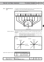
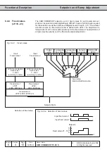
Страница 160: ...6 4 KEB COMBIVERT F5 M S 2 Name Basis 12 05 04 Chapter Section Page Date KEB Antriebstechnik 2002 All Rights reserved Functional Desription Setpoint and Ramp Adjustment...
Страница 161: ...iplies an analog setpoint to with other setpoint settings The setpoint and rotation selection links the different setpoint sources with the possible sources of rotation direction The signal thus obtai...
Страница 162: ...the setpoints can occur either before or after the signal processing ru 27 32 53 With parameter oP 3 Absolute digital setpoint adjustment a setpointspeed of 4000 4000 rpm can be adjusted With paramete...
Страница 163: ...s must be accepted The setpoint limitations oP 6 oP 7 oP 11 do not have any function the speed setpoint is only limited by oP 14 The calculation formula of the analog setpoint value changes The parame...
Страница 164: ...s of ru 82 ramp output 150992 converted in Hz Ramp output Hz ru 82 oP 64 2 30 0 0140622 Hz ru 83 actual value 134217 and in each eight cycle 268434 converted in Hz Actual value ru 83 oP 64 2 30 0 0125...
Страница 165: ...hich the rotation direction is adjusted One can choose between following possibilities Digital rotation adjustment oP 2 oP 2 Display Setpoint rotation 0 LS Standstill Low Speed 1 F Forward Forward 2 r...
Страница 166: ...Bit No Decimal value Input Terminal 0 1 ST Prog input Control release Reset X2A 16 1 2 RST Prog input Reset X2A 17 2 4 F Prog input Forward X2A 14 3 8 R Prog input Reverse X2A 15 4 16 I1 Prog input 1...
Страница 167: ...direction forward negative value rotaiton direction reverse Rotation direction dependent on the control word SY 50 The control word is used for the status control of the inverter via bus In order for...
Страница 168: ...y for the fixed values The adjustment of a fixed value has priority over the normal setpoint adjustment oP 18 0 2 1 3 5 4 6 7 8 9 f1 f2 f3 t Fig 6 4 4 Fixed values oP 19 Input selection Fixed value 1...
Страница 169: ...limited 5 terminal strip Run Stop setpoint absolute 6 setpoint dependent with LS recognition 7 setpoint dependent without LS recognition 8 control word SY 50 0 limited 9 control word SY 50 0 absolute...
Страница 170: ...f absolute setpoint adjustment the minimal and maximal values limit the setpoint Separate limits can be adjusted for both directions of rotation If the value For is adjusted for rotation direction Rev...
Страница 171: ...formula positive setpoint oP 6 setpoint adjustment x oP 10 oP 6 100 negative setpoint oP 7 setpoint adjustment x oP 11 oP 7 100 the absolute setpoint adjustment i e the setpoint is directly adjusted a...
Страница 172: ...s x 1000 rpm oP 28 4 5 s 1000 rpm 100 rpm 1000 rpm x real ramp time oP 28 oP 31 n A drive shall accelerate from 100 rpm to 1000 rpm in 5s Example Time factor acceleration deceleration oP 62 The time f...
Страница 173: ...curve time acceleration forward oP 33 1 S curve time acceleration reverse oP 34 3 S curve time deceleration forward oP 35 1 S curve time deceleration reverse 1 If the value For is adjusted in these p...
Страница 174: ...d at the same time The belts reduce the speed in proportion to the adjusted time and come to a standstill simultaneously 6 4 9 Ramp with constant time f_soll f_ist t t_rampe t_rampe t_rampe t_rampe t_...
Страница 175: ...3 reserved 0 const ascent 1000 rpm dep on ud 2 Dec 2 3 4 const time actual set value Vorward 8 const time last set value at constant run 12 reserved 0 const ascent 1000 rpm dep on ud 2 Acc 4 5 16 cons...
Страница 176: ...ulated from the step size delta_n and the actual set value n_set as follows n_soll delta_n variable delta_n 1000 rpm For a simplification of the internal calculations 1024 min 1 resp 2048 min 1 or 409...
Страница 177: ...1 16 oP 20 0314h 0 4095 1 32 oP 21 0315h 4000 rpm 4000 rpm 0 125 rpm 100 rpm dep on ud 2 oP 22 0316h 4000 rpm 4000 rpm 0 125 rpm 100 rpm dep on ud 2 oP 23 0317h 4000 rpm 4000 rpm 0 125 rpm 0 rpm dep...
Страница 178: ...etpoint and Ramp Adjustment oP 65 0341h 4000 min 1 4000 min 1 0 125 min 1 0 min 1 oP 66 0342h 4000 min 1 4000 min 1 0 125 min 1 0 min 1 oP 67 0 43h 4000 min 1 4000 min 1 0 125 min 1 0 min 1 oP 68 0344...
Страница 179: ...ment 6 6 Motor Data Adjustment 6 7 Protective Functions 6 8 Parameter Sets 6 9 Special Functions 6 10 Encoder Interface 6 11 SMM Posi Synchron CTM 6 12 Technology Control 6 13 CP Parameter Definition...
Страница 180: ...6 5 KEB COMBIVERT F5 2 Name Basis 04 05 04 Chapter Section Page Date KEB Antriebstechnik 2002 All rights reserved Functional Description U f Characteristic Adjustment...
Страница 181: ...peed dependent parameters The parameter can only be written with opened control release After a change the initialization is passed through so that no Power On Reset is necessary ud 2 Control typ Maxi...
Страница 182: ...ncreased in this stage up to 200 see Fig 6 5 2 uF 0 0 0000 400 00 Hz Default 50 Hz uF 1 0 0 25 5 Default PU Id UA t uF 1 100 uF 5 uF 4 uF 4 0 0 25 5 Default 0 uF 5 0 00 10 00 s Default 0 s 6 5 4 Delta...
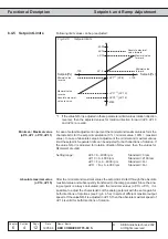
Страница 183: ...otors with a smaller rated current to the inverter uF 9 1 649 V 650 off default Fig 6 5 5 a Voltage stabilization with voltage stabilization without voltage stabilization Fig 6 5 5 b Example Accelerat...
Страница 184: ...factor 1 110 U f 110 voltage with overmodulation all limitations 110 of modulation factor 2 200 U f 100 voltage limitations between voltage forming functions 200 limitation before modulator 100 of mod...
Страница 185: ...0 0 uF 4 0504h 0 0 25 5 0 1 0 0 uF 5 0505h 0 00 s 10 00 s 0 01 s 0 00 s uF 9 0509h 1 V 649 V 650 off 1 V 650 off uF 10 050Ah 0 3 1 0 uF 11 050Bh 0 PU Id 1 PU Id PU Id Power unit Identification uF 19...
Страница 186: ...6 5 KEB COMBIVERT F5 8 Name Basis 04 05 04 Chapter Section Page Date KEB Antriebstechnik 2002 All rights reserved Functional Description U f Characteristic Adjustment...
Страница 187: ...ment 6 5 Voltage Frequency Characteristic Adjustment 6 6 Motor Data and Controller 6 7 Protective Functions 6 8 Parameter Sets 6 9 Special Functions 6 10 Encoder Interface 6 11 Posi Synchronous Contro...
Страница 188: ...6 6 KEB COMBIVERT F5 M S 2 Name Basis 12 05 04 Chapter Section Page Date KEB Antriebstechnik 2002 All Rights reserved Functional Desription Motor Data and Controller...
Страница 189: ...rom it which the inverter requires to achieve the best possible results in the control of Boost and slip compensation 6 6 2 Motor Data DASM Following parameters can be taken directly from the name pla...
Страница 190: ...here is usually R120 equivalent resistance phase value specified Depending on the used connection the following value must be adjusted in dr 6 Star connection dr 6 2 R120 to 2 24 R120 Delta connection...
Страница 191: ...LS L1 Lh Lh 2 L1 L2 L2 Lh In accordance with the following formula the leakage inductance LS in a range of 0 00 500 00 mH is entered in parameter dr 7 In case the data is not specified in the data she...
Страница 192: ...motor current that is too high Vorgehensweise 1 Open control release status noP 2 Enter motor name plate data in the corresponding parameters dr 0 12 3 Adjust Fr 10 1 or Fr 10 2 the corresponding dr d...
Страница 193: ...is limited by 2 further factors If the KEB COMBIVERT is dimensioned too small to operate the current that is necessary for the required torque then the maximum torque is limited automatically From the...
Страница 194: ...ening characteristic is adjusted The value of 1 means that the flux is lowered after an 1 n function 6 6 5 Flux Lowering Calculation DASM field weakening speed dr 18 Field weakening curve dr 20 Flux a...
Страница 195: ...phase synchronous motor DSM and entered dr 23 DSM rated current 1 0 710 0 A dr 24 DSM rated speed 0 32000 rpm dr 25 DSM rated frequency 10 1600 0 Hz dr 27 DSM rated torque 0 1 6553 5 Nm Motor data fr...
Страница 196: ...h 0 01 Nm 10000 Nm 0 01 Nm Adaption only F5 M dr 17 0611h 1 rpm 32000 rpm 1 rpm Adaption only F5 M dr 18 0612h 0 rpm 32000 rpm 1 rpm Adaption only F5 M dr 19 0613h 25 250 1 Adaption only F5 M dr 20 06...
Страница 197: ...or the torque control At F5 S it can be switched only between speed and torque control A controlled operation is not possible PG ASM 3 Usd Usq F F Umax U V W r d q r Fig 6 6 8 Controller structure nse...
Страница 198: ...changed with dr 21 at F5 M and with dr 26 at F5 S KP current dS 0 KI current dS 1 Restrictions for controlled operation The controlled operation is suited only as emergency operation for set up or in...
Страница 199: ...ange particularly at activated rotor adaption in order to limit the voltage in the field weakening range to 100 5 6 0 Flux controller off 1 Flux controller on sensible for short acceleration times and...
Страница 200: ...KI cS 11 Min speed for cS 9 cS 12 Fig 6 6 11 Mode of functioning of the speed controller Picture A Picture B To improve the standstill rigiditiy of the drive a standstill position control can be adjus...
Страница 201: ...2 Digital absolute cS 19 3 Digital precental cS 18 4 Motorpoti 5 External PID output technology controller 6 6 12 Torque control at cS 0 5 0 1 2 3 4 5 cS 15 cS 19 cS 16 ru 49 1 0 abs abs Speed contro...
Страница 202: ...01 10000 Nm 0 01 Nm 0 01 at 0 01 cS 19 also acts as a limit cS 22 0F16h 0 01 10000 Nm 0 01 Nm 0 01 at 0 01 cS 19 also acts as a limit cS 24 0F18h 0 32767 1 0 0 off ru 47 022Fh 10000 Nm 10000 Nm 0 01 N...
Страница 203: ...Ramp Adjustment 6 5 Voltage Frequency Characteristic U f Adjustment 6 6 Motor Data Adjustment 6 7 Protective Functions 6 8 Parameter Sets 6 9 Special Functions 6 10 Encoder Interface 6 11 SMM Posi Sy...
Страница 204: ...6 7 KEB COMBIVERT F5 2 Name Basis 04 05 04 Chapter Section Page Date KEB Antriebstechnik 2002 All rights reserved Functional Description Protective Functions...
Страница 205: ...A Stop 0 off off off 1 off off on 2 off on off 3 off on on 4 on off off 5 on off on 6 on on off 7 on on on LA Stop The function protects the frequency inverter against switch off caused by overcurrent...
Страница 206: ...f Hardware current limit disabled 1 Single phase mode Hardware current limit enabled works both in motoric and generatoric operation 2 Zero vektor mode Hardware current limit enabled works only motori...
Страница 207: ...ntrol direction inverts itself during generatoric operation Control direction independent on active current Control direction is inverted in the case of negative active current generatoric operation T...
Страница 208: ...ng of Stall function with standard setting Actual frequency ru 3 Inverter status ru 0 Actual utilization ru 13 adjusted constant current limit Pn 20 Stall level The max constant current represents the...
Страница 209: ...ts the connection of the frequency inverter onto a running out motor After the function has been activated by the selected starting conditions Pn 26 it searches for the actual motor speed and adapts t...
Страница 210: ...PROG R W Step Fig 6 7 3 b Speed search with soft adjusted function Actual speed Motor speed Utilization Output voltage Speed search Ramp Error Reset Actual speed Motor speed Utilization Output voltage...
Страница 211: ...Input selection external error Pn 3 Response to external fault Pn 6 Watchdog time Pn 5 Response to error watchdog Pn 7 Response to limit switch Pn 18 Response to set warning Pn 66 Response to soft li...
Страница 212: ...he drive returns automatically to normal operation as soon as the fault no longer exists Status message A xx Fast stop switch off of modulation after reaching 0Hz The drive returns automatically to no...
Страница 213: ...f 0 200 C On exceeding the adjusted temperature the turn off time Pn 13 starts the switching condition 46 is set and the response according to Pn 12 is executed After expiration of the turn off time t...
Страница 214: ...The drive remains in the error status until a reset signal is detected No effect on the drive Error is being ignored Switching condition do 0 7 Value 11 is set Function disabled interior temperature...
Страница 215: ...s to 100 Hz 1000 rpm depending on ud 2 Adjustment of the torque limit during fast stop in the range of 0 10000 Nm Pn 61 is limited to dr 15 max torque FI and dr 33 three phase motor dr 15 dr 33 cS 19...
Страница 216: ...h 0 s 120 s 1 s 0 s Pn 18 0412h 0 6 1 0 Pn 58 043Ah 0 3 1 0 only for F5 G Pn 59 043bh 0 200 1 200 only for F5 G Pn 60 043Ch 0 00 s 300 00 s 0 01 s 2 00 s Pn 61 043Dh 0 00 Nm 10000 00 Nm 0 01 Nm Adapti...
Страница 217: ...or protection 0 Separate cooling 1 Self cooling ru 15 Apparent current dr 12 Motor protect rated current 0 1 460 0 A fr 8 Motor set assignemet 0 Counter 0 1 Counter 1 2 Counter 2 3 Counter 3 4 Counter...
Страница 218: ...ted After triggering the motor protective function the new tripping time is reduced to 1 4 of the specified value if the motor has not been operated for an appropriate time with underload Motor protec...
Страница 219: ...warning also see Digital Outputs is set Pn 14 determines the response to the warning level Pn 14 specifies the performance of the drive on activation of the motor protective function The function is d...
Страница 220: ...10 0 s 0 1 s 0 5 s only at F5 S dr 35 0623 0 1 s 10 0 s 0 1 s 0 2 s only at F5 S dr 36 0624 0 1 s 10 0 s 0 1 s 5 0 s only at F5 S ru 15 020Fh 0 0 A 6553 5 A 0 1 A The KEB COMBIVERT provides another po...
Страница 221: ...n 65 the switching behaviour of the GTR7 can be adjusted as follows Pn 65 Switching behaviour GTR7 0 not in status LS default 1 also switches at LS With Pn 64 an input can be defined for the activatio...
Страница 222: ...riggered at the switching of an external error input Pn 4 0 Pn 4 is selection for external error warning message The response to this message A EF E EF is defined with Pn 3 1 Pn 4 is selection for err...
Страница 223: ...Adjustment 6 5 Voltage Frequency Characteristic U f Adjustment 6 6 Motor Data Adjustment 6 7 Protective Functions 6 8 Parameter Sets 6 9 Special Functions 6 10 Encoder Interface 6 11 SMM Posi Synchron...
Страница 224: ...6 8 KEB COMBIVERT F5 2 Name Basis 05 05 04 Chapter Section Page Date KEB Antriebstechnik 2002 All rights reserved Functional Description Parameter Sets...
Страница 225: ...ogrammable parameters 6 8 2 Security Parame ters The Security parameters contain the Baud rate inverter address hours meter control type serial customer number trimming values and error diagnosis They...
Страница 226: ...states occur ini_A ini_S dEF_A Target Set Source Set Action 0 7 0 7 All programmable parameters System parameters too of the source set are copied into the target set 0 1 dEF_S Default values are copi...
Страница 227: ...ection input coded via terminal strip Priority ST RST R F I1 I2 I3 I4 IA IB IC ID 4 Set selection input coded via terminal strip Priority ID IC IB IA I4 I3 I2 I1 R F RST ST 5 Set selection via control...
Страница 228: ...Adjust parameter Fr 7 to value 148 2 Adjust Fr 2 to value 2 set selection binary coded via terminal strip 1 The input ST is occupied by hardware means with the function Control release Further functi...
Страница 229: ...parameter Fr 7 to value 2736 2 Adjust Fr 2 to value 3 set selection input coded via terminal strip 0 1 2 3 4 5 I1 I2 I4 IB ID Set Set Set Set Set Set Fig 6 8 7 c Input coded parameter set selection F...
Страница 230: ...8 9 ON and OFF delay Example on off Set Fr 5 Fr 6 0 0 s 0 s 1 2 s 0 s 2 0 s 1 s 3 2 s 2 s 1 ON delay for set 3 of 2s 2 OFF delay for set 3 of 2s 3 OFF delay for set 2 of 1s ON delay for set 1 of 2 s 4...
Страница 231: ...al Description Parameter Sets Param Adr min max default ENTER PROG R W Step 6 8 10 Used Parameters Fr 1 0901h 4 7 1 0 Fr 2 0902h 0 5 1 0 Fr 3 0903h 0 255 1 0 Fr 4 0904h 0 7 1 0 Fr 5 0905h 0 32 00 s 0...
Страница 232: ...6 8 KEB COMBIVERT F5 10 Name Basis 05 05 04 Chapter Section Page Date KEB Antriebstechnik 2002 All rights reserved Functional Description Parameter Sets...
Страница 233: ...Adjustment 6 7 Protective Functions 6 8 Parameter Sets 6 9 Special Functions 6 10 Encoder Interface 6 11 SMM Posi Synchron 6 12 Technology Control 6 13 CP Parameter Definition 6 9 1 KEB COMBIVERT F5 N...
Страница 234: ...6 9 KEB COMBIVERT F5 2 Name Basis 04 05 04 Chapter Section Page Date KEB Antriebstechnik 2002 All rights reserved Functional Description Special Functions...
Страница 235: ...ence value 1 Act brake time Pn 30 Pn 32 reference value 1 Pn 28 DC Braking Activation 0 DC braking not activated 1 DC braking after reaching 0Hz rpm and missing rotation setting max for the adjusted D...
Страница 236: ...ENTER PROG RO Step DC Braking Mode Pn 28 Used Parameters Pn 28 041Ch 0 9 1 7 Pn 29 041Dh 0 4095 1 64 Pn 30 041Eh 0 00 100 00 s 0 01 s 10 00 s Pn 31 041Fh 0 25 5 0 1 25 5 Pn 32 0420h 0 400 Hz 0 0125 Hz...
Страница 237: ...s a result of the voltage reduction uF 7 Energy saving factor 0 0 130 0 default 70 fset nset Hysteresis Example uF 6 2 uF 7 50 Used Parameters uF 6 0506h 0 79 1 0 uF 7 0507h 0 0 130 0 1 70 uF 8 0508h...
Страница 238: ...6 9 KEB COMBIVERT F5 6 Name Basis 04 05 04 Chapter Section Page Date KEB Antriebstechnik 2002 All rights reserved Functional Description Special Functions...
Страница 239: ...Prog input 2 X2A 11 6 64 I3 Prog input 3 X2A 12 7 128 I4 Prog input 4 X2A 13 8 256 IA Internal input A none 9 512 IB Internal input B none 10 1024 IC Internal input C none 11 2048 ID Internal input D...
Страница 240: ...defined which the motor potentiometer needs in order to run from 0 100 The time is adjustable between 0 50000 s The correcting range is limited by the parameters oP 53 and oP 54 see Fig 6 9 3 This pa...
Страница 241: ...with other percental setpoint sources see Chapter 6 4 Set Value Adjustment Motor potentiometer value oP 52 With this parameter a value in percent can be adjusted within the preset limits directly by o...
Страница 242: ...6 9 KEB COMBIVERT F5 10 Name Basis 04 05 04 Chapter Section Page Date KEB Antriebstechnik 2002 All rights reserved Functional Description Special Functions...
Страница 243: ...ts again at zero The timer stops at the maximal value of 655 35 Following clock sources can be selected Bit Value Function 0 2 Clock source 0 Time counter 0 01 s default 1 Time counter 0 01 hour 2 Edg...
Страница 244: ...rrent counter content ru 43 44 Bit No Decimal value Input Terminal 0 1 ST prog input control release Reset X2A 16 1 2 RST prog input Reset X2A 17 2 4 F prog input forward X2A 14 3 8 R prog input rever...
Страница 245: ...18 23 0 01 0 LE 2 0D02h 10737418 24 10737418 23 0 01 0 LE 3 0D03h 10737418 24 10737418 23 0 01 0 LE 4 0D04h 10737418 24 10737418 23 0 01 0 LE 5 0D05h 10737418 24 10737418 23 0 01 0 LE 6 0D06h 10737418...
Страница 246: ...6 9 KEB COMBIVERT F5 14 Name Basis 04 05 04 Chapter Section Page Date KEB Antriebstechnik 2002 All rights reserved Functional Description Special Functions...
Страница 247: ...m utilization level Pn 43 If the utilization is less than this level or the hardware current limit is reached the error E br is triggered and the brake remains engaged If the utilization acceptance is...
Страница 248: ...monitoring The status display during the holding phases depends on the setting of the mode for the brake control see Fig 6 9 5 c At Pn 34 1 3 the status boff release brake or bon engage brake is disp...
Страница 249: ...0 Hz F5 M S depending on ud 2 Pn 39 0427h 0 00 s 100 00 s 0 01 s 0 25 s Pn 40 0428h 0 00 s 100 00 s 0 01 s 0 25 s Pn 41 0429h 20 Hz 20 Hz 0 0125 Hz 0 Hz F5 G B depending on ud 2 0429h 600 rpm 600 rpm...
Страница 250: ...6 9 KEB COMBIVERT F5 18 Name Basis 04 05 04 Chapter Section Page Date KEB Antriebstechnik 2002 All rights reserved Functional Description Special Functions...
Страница 251: ...6 9 6 a Starting the Power Off function Auto DC link voltage set value measured at Power on Pn 45 starting voltage 200 800 V Pn 46 Auto start voltage 50 90 default 80 Pn 44 Bit 1 starting voltage 0 a...
Страница 252: ...alue 0 of 1 or as active current control without speed detection value 2 Normally this parameter is adusted at the setup of the speed control see Chapter 6 11 and should not be changed here The parame...
Страница 253: ...voltage is measured at Power On and is displayed in ru 68 The auto starting voltage is determined by Pn 46 which adjusts the measured voltage in percent in the range of 50 90 default 80 of the measur...
Страница 254: ...etpoint value is limited internally which can lead to oscillations In that case the setpoint value can be reduced which leads to a prolongation of the delay If the voltage stabilisation is switched on...
Страница 255: ...ependent of a set direction of rotation with the adjusted boost and is in status POFF After expiration of the restart delay Pn 52 if adjusted the inverter restarts automatically Bit 3 0 and Bit 4 1 th...
Страница 256: ...this range to prevent stalling Below the restart value the control parameters of the active current control are lowered linearly with the output frequency Set value source Braking torque Pn 47 Pn 44...
Страница 257: ...dapted to slow voltage fluctuations In the first cycle the limit of the speed control is adjusted to the measured slip so that the drive is put into no load operation Restart at power recovery Only in...
Страница 258: ...0 1 80 Pn 47 042Fh 0 0 100 0 0 1 0 only F5 G B Pn 48 0430h 0 Hz 400 Hz 0 0125 Hz 0 Hz only F5 G B 0430h 0 min 1 4000 min 1 0 125 min 1 0 min 1 only F5 M dep on ud 2 Pn 50 0432h 200 V 800 V 1 V 290 500...
Страница 259: ...ivated with oP 44 Bit 0 3 The value is to be added to Bit 4 7 oP 44 Bit 0 3 Function 0 no external function activated 1 Wobbel generator acitvated 2 Diameter correction see Chapt 6 9 8 3 15 reserved T...
Страница 260: ...2Eh 0 00 s 20 00 s 0 01 s 10 00 s oP 47 032Fh 0 00 s 20 00 s 0 01 s 10 00 s oP 48 0330h 0 00 s 20 00 s 0 01 s 10 00 s Wobbel generator Acceleration time oP 47 Deceleration time oP 48 With oP 47 the ac...
Страница 261: ...eter of the reel bale Additional function Mode oP 44 Bit 0 3 Different functions can be activated with oP 44 Bit 0 3 The value is to be added to Bit 4 7 oP 44 Bit 0 3 Function 0 no external function a...
Страница 262: ...ameter dmin dmax is preset by way of oP 49 and can be adjusted within the range of 0 010 0 990 with a resolution of 0 001 The corrected output frequency of the ramp generator is determined as follows...
Страница 263: ...oning With parameter Pn 63 a shifting of the stop position can be adjusted which entails an additional constant running time Thus the shifting of the initiator can be omitted The additional constant r...
Страница 264: ...Set 1 positioning 1 oP02 Rotation setting 0 low speed 0 1 oP10 Max reference forward 70 0000 Hz The max setpoint value must be the same in all sets 0 1 oP28 Acc time forward 0 01 s 0 1 oP30 Dec time f...
Страница 265: ...ng of the position at clockwise rotation 2 Pn63 Positioning delay 1 off 3 Pn63 Positioning delay 3 1 s Shifting the position at counterclockwise rotation 0 Fr02 Parameter set source 2 terminal binary...
Страница 266: ...hat adjusts itself at 100 analog parameter setting The parameter value must be entered with the internal standardization of the target parameter An 57 determines the parameter set in which the selecte...
Страница 267: ...ustment 6 6 Motor Data Adjustment 6 7 Protective Functions 6 8 Parameter Sets 6 9 Special Functions 6 10 Encoder Interface 6 11 SMM Posi Sync CTM 6 12 Technology Control 6 13 CP Parameter Definition 6...
Страница 268: ...6 10 KEB COMBIVERT F5 2 Name Basis 17 02 03 Chapter Section Page Date KEB Antriebstechnik 2002 All rights reserved Functional Description Encoder Interface...
Страница 269: ...Encoder channel 1 X3A is a 15 pole incremental encoder input for rectangular signals Encoder channel 2 X3B can support following interfaces 9 pole incremental encoder input for rectangular singal Incr...
Страница 270: ...signal inputs must generally be connected The reference marking singals are only needed for the reference point approach in the positioning operation F5 M S Following specifications apply to the enco...
Страница 271: ...Resolver cable 6 10 3 Encoder Inteface Channel 2 X3B Fig 6 10 3 Encoder interface channel 2 X3B 5 4 3 2 1 9 8 7 6 Only when the inverter is switched off and the voltage supply is disconnected may the...
Страница 272: ...us operation Operating mode encoder 2 ec 20 With parameter ec 20 it is defined whether the encoder channel 2 shall work as input or output Precondition for that is a built in switch selectable encoder...
Страница 273: ...be supplied with an external voltage The 5 V voltage is a stabilized voltage and loadable at X3A and X3B with altogether 500 mA Since 5 2 V are generated from Uvar the current from Uvar is reduced ac...
Страница 274: ...onnection Max operating frequency max sampling frequency Depending on the max operating frequency of the encoder input the encoder and the maximum speed of the drive the line number of the encoder can...
Страница 275: ...y evaluated The zero track is needed for the reference point approach in the positioning module F5 M S Zero track also reference marking channel gives out 1 signal per revolution Cable length To achie...
Страница 276: ...r input 24 V HTL with error detection push pull 16 ENDAT 17 Incremental encoder input 24 V HTL with error detection 18 Analog option 10 V In case of an invalid encoder indentification the error E Hyb...
Страница 277: ...10 Gear factor Ec 4 Ec 5 Ec 14 Ec 15 Value Evaluation of the encoder signals 0 Single for initiator evaluation of positive edges only 20 1 2 fold for initiator evaluation of positive and negative edg...
Страница 278: ...coder simulation can be adjusted Bit Value Function 0 1 Acceptance of the values 0 from channel 1 1 from channel 2 2 from current actual value 2 3 Number of increments to be output at Bit 0 1 2 0 256...
Страница 279: ...sed the value determined by the automatic alignment can be entered directly in Ec 2 12 Absolute position channel 1 2 Ec 2 Ec 12 only F5 S In order to replace S4 systems by F5 S the following calculati...
Страница 280: ...the encoder may not lead to a jump in the actual position ru r4 2 After power off on the position value ru 54 must be available Conclusion the overflow of the encoder must be noticed For this the pos...
Страница 281: ...e motor data are read out with the first power on with encoder Acknowledgement of the encoder interface change E HYPC via ec 0 Loading the system default value fr 1 3 or 4 the motor data are read out...
Страница 282: ...0000 1 1000 Ec 15 gear 2 determinator 100F x 1 10000 1 1000 Ec 16 enc 2 rotation 1010 x 0 23 1 0 Ec 17 enc 2 trigger 1011 x 0 13 1 2 GBK encoder Id Ec 20 enc 2 operating mode 1014 x 0 1 1 GBK Ec 21 SS...
Страница 283: ...6 4 Setpoint and Ramp Adjustment 6 5 Voltage Frequency Characteristic Adjustment 6 6 Motor Data and Controller 6 7 Protective Functions 6 8 Parameter Sets 6 9 Special Functions 6 10 Encoder Interface...
Страница 284: ...6 11 KEB COMBIVERT F5 M S 2 Name Basis 06 05 04 Chapter Section Page Date KEB Antriebstechnik 2002 All Rights reserved Functional Desription Positioning and Synchronous Control...
Страница 285: ...e 6 Contouring mode 7 Activation by control word Bit 3 9 Posi mode for Posi module only see chapter 6 11 7 Bit 10 Start synchronous with ramp oP 28 0 The synchronizing after Start Synchronous does not...
Страница 286: ...osition difference to overshootings With PS 5 a synchronization position can be preset in increments which the master must cover before it runs angular synchronous with the slave If on activating the...
Страница 287: ...to earlier units the preset value is adjusted to 250 rpm If a gear ratio is to be created between the master and the slave drive it is done with the parameters Ec 4 5 or Ec 14 15 see Chapter 6 10 Gear...
Страница 288: ...ompleting the reference point approach the actual position is overwritten with the reference point PS 17 and the switching condition reference point approach completed do 0 do 7 value 29 is set The ra...
Страница 289: ...efines the max speed to reach the position in index 0 Index 0 is not available for further positioning par example Mode PS 31 25 target speed unequal 0 0 No 128 With valid position the output function...
Страница 290: ...ne 9 512 IB internal input B none 10 1024 IC internal input C none 11 2048 ID internal input D none Referenz acc dec time PS 20 Limit switch left PS 15 Limit switch right PS 16 With these parameters t...
Страница 291: ...ight di 19 32 Terminal X2A 15 limit switch left reference point switch di 20 67108920 Terminal X2A 10 start reference point approach di 11 134217728 Reference speed 100 rpm with counter clockwise rota...
Страница 292: ...ce point switch di 12 67108864 Terminal X2A 10 Start Reference point approach di 11 134217728 Reference speed 100 rpm with counter clockwise rotation PS 21 100 If the zero impulse is not be approached...
Страница 293: ...ch di 12 67108864 Terminal X2A 10 Start Reference point approach di 11 134217728 Reference speed 100 rpm with counter clockwise rotation PS 21 100 If the zero impulse is not be aprroached PS 14 Bit 2...
Страница 294: ...the following position lies in opposite direction a target speed of 0 min 1 is preset and after reaching it it is continued with the maximum profile speed of the subsequent index If the profile was pr...
Страница 295: ...28 Here PS 5 is the offset from the start input to the position of the slave In the case of a positive offset the start input is thus left from the slave In the Posi Mode PS 1 defines the input for t...
Страница 296: ...The line number of the master is rescaled to the line number of the slave Synchronous and positioning Controller Motor CH 2 CH 1 Controller Motor CH 2 CH 1 Position reference Encoder Encoder Positioni...
Страница 297: ...on The summing up of the basic setting ec 4 ec 5 S1 ec 33 ec 31 ec 29 ec 14 ec 15 S2 ec 34 ec 32 ec 30 ru 54 Position detection Evaluation Gear factor Gear factor Bit No Decimal value Input Terminal 0...
Страница 298: ...with PS 1 Depending on PS 0 bit 4 the positioning target speed is entered here The adjusted values always refer to the controller The setting is done in the range of 4000 min 1 depending on ud 2 This...
Страница 299: ...do 0 7 value 54 is output The adjustment of this target window takes place within the range of 215 215 1 increments If the automatic brake control is to be used in the Posi mode the source of rotation...
Страница 300: ...11 6 64 I3 prog input 3 X2A 12 7 128 I4 prog input 4 X2A 13 8 256 IA internal input A none 9 512 IB internal input B none 10 1024 IC internal input C none 11 2048 ID internal input D none PS 36 specif...
Страница 301: ...mode is only possible at standstill When activating the synchron mode over the bus operator the cycle time is automatically adjusted in Sy 08 If the contouring mode was activated the inverter status r...
Страница 302: ...0 PS15 Limit switch right 130F 230 230 1 1 230 PS16 Limit switch left 1310 230 230 1 1 230 PS17 Reference point 1311 230 230 1 1 0 inc PS18 Reference switch inp sel 1312 ja 0 4095 1 0 PS19 Reference...
Страница 303: ...ent 6 5 Voltage Frequency Characteristic U f Adjustment 6 6 Motor Data Adjustment 6 7 Protective Functions 6 8 Parameter Sets 6 9 Special Functions 6 10 Encoder Interface 6 11 SMM Posi Synchron CTM 6...
Страница 304: ...6 12 KEB COMBIVERT F5 2 Name Basis 04 05 04 Chapter Section Page Date KEB Antriebstechnik 2002 All rights reserved Functional Description Technology Control...
Страница 305: ...ade in reset input selection cn 11 Reset PID input selection cn 12 Reset I input selection cn 10 PID Reset condition cn 9 PID fading time Digital inputs PID controller KP cn 4 Defines the proportional...
Страница 306: ...reset input selection cn 13 Fade in reset input selection Reset by way of digital inputs cn 11 13 With cn 10 it is possible to set the reset conditions for the PID Controller Thus simple speed regula...
Страница 307: ...he set value of the PID Controller is preset digitally in the range of 400 0 400 0 The parameter is set programmable PID reference source cn 0 Parameter cn 0 specifies the input which supplies the add...
Страница 308: ...g input 2 see chapter 6 2 reserved at B control 2 AN3 Signal of the analog input 3 see chapter 6 2 reserved at B control 3 Aux Signal of the Aux input see chapter 6 2 4 cn 3 PID absolute actual value...
Страница 309: ...ller without precontrol e g for pressure temperature level control Dig set value Ana set value Actual value Characteristic amplifier PID controller Characteristic amplifierr An parameter Ramp generato...
Страница 310: ...1 ru 27 ru 29 ru 28 ru 30 cn 4 6 cn 10 ru 52 oP 0 0 ru 2 cn 1 V V ru 1 cS 0 1 cn 7 8 cS 4 Hz cn 14 ru 2 Analog precontrol Digital set value Real value Characteristic amplifier An parameter Characteris...
Страница 311: ...Controller on the analog output Dig set value Ana set value Actual value Characteristic amplifier PID controller Characteristic amplifier An parameter Characteristic amplifier Characteristic amplifier...
Страница 312: ...PID pos limit 0707 X X 400 0 400 0 0 1 400 0 cn 8 PID neg limit 0708 X X 400 0 400 0 0 1 400 0 cn 9 PID fading time 0709 X X 0 01 300 00 0 01 0 00 s 0 01 freq dependend cn10 PID reset condition 070A...
Страница 313: ...Adjustment 6 5 Voltage Frequency Characteristic U f Adjustment 6 6 Motor Data Adjustment 6 7 Protective Functions 6 8 Parameter Sets 6 9 Special Functions 6 10 Encoder Interface 6 11 SMM Posi Synchron...
Страница 314: ...6 13 KEB COMBIVERT F5 2 Name Basis 04 05 04 Chapter Section Page Date KEB Antriebstechnik 2002 All rights reserved Functional Description CP Parameter Definition...
Страница 315: ...ud 16 ud 17 An 4 CP 1 CP 2 CP 36 440 330 200 100 500 ud 16 1 2 36 With ud 15 the CP parameter that is to be edited is determined With ud 16 and ud 17 the CP parameter is defined through its address a...
Страница 316: ...one 0 0 0 0 0 0 0 1 1 0 0 0 0 0 0 0 1 0 2 1 0 0 0 0 0 0 1 1 3 0 1 1 1 1 1 1 1 1 1 255 All Determination of set addressing mode Bit 8 and 9 determine the set addressing mode Bit 8 9 Value Function 0 0...
Страница 317: ...tandardization 4 1 ud 15 1 CP 1 ud 16 0203h Parameter address for ru 3 ud 17 256 Display in the active set 2 ud 15 2 CP 2 ud 16 0315h Parameter address for oP 21 ud 17 4 Setting in set 2 3 ud 15 3 CP...
Страница 318: ...d 19 x Unit selected parameter ud 20 x ud 18 ud 18 Display standardization Divisor Adjusts the divisor in the range of 32767 default 1 The parameter is set programmable not at B control ud 19 Display...
Страница 319: ...alculation mode selected parameter ud 20 x ud 19 CP xx ud 18 ud 19 CP xx selected parameter ud 20 x ud 18 Value 0 64 free free Function Value Representation 0 0 decimal places 256 1 demical place 512...
Страница 320: ...min max default ENTER PROG R W Step 6 13 5 Used Parameters ud 1 0801h 0 9999 1 440 Application ud 15 080Fh 1 36 1 1 ud 16 0810h 1 off 32767 7FFFh 512 0203h div dep on ud 15 ud 17 0811h 0 8191 1 1 ud...
Страница 321: ...unctions 7 Start up 8 Special Operation 9 Error Assistance 10 Project Planning 11 Networks 12 Annex 7 1 1 KEB COMBIVERT F5 Name Basis 04 05 04 KEB Antriebstechnik 2002 All Rights reserved Section Page...
Страница 322: ...7 1 KEB COMBIVERT F5 2 Name Basis 04 05 04 KEB Antriebstechnik 2002 All Rights reserved Start up Chapter Section Page Date...
Страница 323: ...rt damage Should any external damages to the KEB COMBIVERT be visible get in touch with your forwardig agent and return the unit with a corresponding report to KEB Check the voltage class Absolutely c...
Страница 324: ...d and well contacted Ensure that mains and motor cables are not interchanged as that will lead to the destruction of the inverter Is the motor connected in phase Check tacho initiator and encoder for...
Страница 325: ...Start up 7 1 Preparatory Measures 7 2 Initial Start up 1 Introduction 2 Summary 3 Hardware 4 Operation 5 Parameter 6 Functions 7 Start up 8 Special Operation 9 Error Assistance 10 Project Planning 11...
Страница 326: ...Initial Start up Start up 7 2 KEB COMBIVERT F5 M S 2 Name Basis 18 05 04 Chapter Section Page Date KEB Antriebstechnik 2002 All Rights reserved...
Страница 327: ...ter uF 1 6 Enter encoder line number inc r Parameter Ec 1 11 7 Not cut off frequency of the encoder flimit increments nmax 60 Hz and interface e g encoder inc r 2500 max set speed 3000 rpm flimit 125...
Страница 328: ...input Channel A ru 01 Set speed Channel B ru 07 Actual speed Go in the operating mode of SCOPE calibrate channels and adjust time reference e g 50ms DIV Switch control release X2A 16 Preset fixed spee...
Страница 329: ...lem Sustained oscillation long billowy Solution Reduce I fraction cS 9 and or reduce P fraction cS 6 Problem Very long transient process but stabilization during constant run Solution Increase P fract...
Страница 330: ...Initial Start up Start up 7 2 KEB COMBIVERT F5 M S 6 Name Basis 18 05 04 Chapter Section Page Date KEB Antriebstechnik 2002 All Rights reserved...
Страница 331: ...Annex 8 1 1 KEB COMBIVERT F5 Name Basis 10 04 02 Section Page Date KEB Antriebstechnik 2002 All rights reserved Chapter 8 1 Temperature Control 8 1 1 Parameter Description 3 8 1 2 Possibilities for a...
Страница 332: ...8 1 KEB COMBIVERT F5 2 Name Basis 10 04 02 Special Operation Chapter Section Page Date KEB Antriebstechnik 2002 All Rights reserved...
Страница 333: ...s the cycle time in which the output is switched The period can be adjusted in a range from 1 0 240 0 s The heat sink temperature which shall be controlled is entered with Offset The temperature is in...
Страница 334: ...rol of the valve see the following fig do xx do xy a Temperature Control with Temperature Monitoring in the Motor In this case the motor is without temperature monitoring The motor can be permanently...
Страница 335: ...with clips note flow direction and check tightness The connection to the cooling system is done via 1 2 inch secrewed glands Whitworth pipe thread of DIN ISO 228 1 The connection to the cooling syste...
Страница 336: ...it Inflow Outflow Valve KEB COMBIVERT Dependent on the power unit and overload capacity the inverter Off temperatures are60 C 73 Cor90 C To ensure a safe operation the coolant output temperature must...
Страница 337: ...sinks are sealed with sealing rings and by bonding dismountable screwed and they have a surface protection in the channels anodized As standard the heat sinks are maintenance free There are no specia...
Страница 338: ...ondition SB 7 43 ANOUT4 PWM do 23 Selection SB for Flag 7 128 SB7 do 34 Selection of Flag for O2 128 M7 do 00 Switching Condition SB 0 3 Ready for Operation do 16 Selection of SB for Flag 0 1 SB0 do 3...
Страница 339: ...5 Parameter 6 Functions 7 Start up 8 Special Operation 9 Error Assistance 10 Project Planning 11 Networks 12 Annex 1 9 1 1 KEB COMBIVERT F5 Name Basis 04 05 04 Section Page Date KEB Antriebstechnik 20...
Страница 340: ...9 1 KEB COMBIVERT F5 2 Name Basis 04 05 04 Error Assistance Chapter Section Page Date KEB Antriebstechnik 2002 All Rights reserved...
Страница 341: ...the appropriate error in the display Error messages cause the immediate deactivation of the modulation Restart possible only after reset Malfunction are represented with an A and the appropriate mess...
Страница 342: ...usted ramp times in anti clockwise direction of rotation rcon reverse constant 69 The acceleration deceleration phase is completed and it is driven with constant speed frequency in anti clockwise dire...
Страница 343: ...ecification Encoder has an internal error E EnCC Error Encoderchange 35 Operation of a synchronous motor with intelligent interface Encoder is not connected during the start Encoderwaschanged The erro...
Страница 344: ...30 Electronic motor protective relay has tripped E OHI ERRORoverheatinternal 6 Error Overheating in the interior error can only be reset at E nOHI if the interior temperature has dropped by at least...
Страница 345: ...ly at F5 G B housing E SbuS ERROR bus synchron 23 Sychronization over sercos bus not possible Programmed response Error restart after reset see chapter 6 7 Response to errors or warning messages E SEt...
Страница 346: ...pow mod 89 A level can be defined when it is exceeded this warning is output A response to this warning can be programmed see chapter 6 7 Response to errors or warning messages A OH2 ABN STOP motor pr...
Страница 347: ...set The response to this warning can be programmed see chapter 6 7 Response to errors or warning messages A SLF ABN Software limit switch forward 104 The target position lies outside of the limit defi...
Страница 348: ...9 1 KEB COMBIVERT F5 10 Name Basis 04 05 04 Error Assistance Chapter Section Page Date KEB Antriebstechnik 2002 All Rights reserved...
Страница 349: ...2 All Rights reserved 10 1 General Design 1 Introduction 2 Summary 3 Hardware 4 Operation 5 Parameter 6 Functions 7 Start up 8 Special Operation 9 Error Assistance 10 Project Planning 11 Networks 12 A...
Страница 350: ...Project Planning 1 2 10 Name Basis KEB COMBIVERT F5 04 05 04 Chapter Section Page Date KEB Antriebstechnik 2002 All Rights reserved...
Страница 351: ...t Design Calculation Controlcabinetsurface Calculation of control cabinet surface PV A m2 T K Air flow rate with fan cooling 3 1 PV V m3 h T A control cabinet surface m2 T temperature differential K s...
Страница 352: ...ated time it is necessay to use a braking resistor tB tBmin 4 Calculate braking torque MB Take the load torque into account at the calculation 5 Calculate peak braking power PB The peak braking power...
Страница 353: ...rakingtorque necessary Nm ML loadtorque Nm tB braking time necessary s tBmin minimum braking time s tZ cycle time s PB peakbrakingpower W PR peak power of braking resistor W K 0 25 for motors up to 1...
Страница 354: ...31 10 mm 2 x 4 mm 61 53 51 43 16 mm 2 x 6 mm 82 71 69 58 25 mm 2 x 10 mm 108 94 91 77 35 mm 2 x 16 mm 135 117 113 96 50 mm 2 x 16 mm 168 146 141 119 70 mm 2 x 25 mm 207 180 174 147 95 mm 2 x 35 mm 250...
Страница 355: ...r Assistance 10 Project Planning 11 Networks 12 Annex 11 1 1 KEB COMBIVERT F5 Name Basis 04 05 04 KEB Antriebstechnik 2002 All rights reserved Chapter Section Page Date 11 1 1 Available Hardware 3 11...
Страница 356: ...11 1 2 Name Basis KEB COMBIVERT F5 04 05 04 KEB Antriebstechnik 2002 All rights reserved Chapter Section Page Date Network Hardware Networks...
Страница 357: ...s Operator Part No 00 F5 060 4000 InterBus Remote bus interface connection Part No 00 B0 0BK K001 in connection with Interface Operator F5 CanOpen Operator Part No 00 F5 060 5000 F5 Sercos Operator Pa...
Страница 358: ...RxD B ReceivesignalB RS485 6 VP Supply voltage Plus 5V Imax 10mA 7 GND Data reference potential earth for VP 8 TxD A TransmissionsignalA RS485 9 TxD B TransmissionsignalB RS485 11 1 4 Interface Opera...
Страница 359: ...ace pin connector ANTRIEBSTECHNIK START STOP FUNC SPEED ENTER F R PBS1 PBS2 ANTRIEBSTECHNIK Diag E PAR PDOUT PDIN The PROFIBUS DP interface module realizes a passive user Slave This means that the PRO...
Страница 360: ...Remote bus cable not available or defective host not in operation or defective E red On Ready for operation Blinking Inverter failure Off No supply voltage RC green On Remote bus ready for operation...
Страница 361: ...can completely send his telegram without repeating the first part All other nodes go into receiving status and stop sending their telegram The available telegram numbers in the CAN version 2 0A are li...
Страница 362: ...SERCOS output interface The herein described unit is a plugable operator with SERCOS interface for the frequency inverter or servo KEB COMBIVERT F5 As far as possible the hard and software were develo...
Страница 363: ...works 12 Annex 11 2 1 KEB COMBIVERT F5 Chapter Section Page 04 05 04 Date Name Basis KEB Antriebstechnik 2002 All rights reserved 11 2 1 Adjustment of Inverter Address 3 11 2 2 Baud Rate ext Bus 3 11...
Страница 364: ...11 2 2 Chapter Section Name Basis KEB Antriebstechnik 2002 All rights reserved Page Date 04 05 04 KEB COMBIVERT F5 Networks Bus Parameters...
Страница 365: ...g Time Pn 6 For a continual check it is possible to trigger an error message of the inverter at the completion of an adjustable time 0 01 10 s during which no telegram is received The function can be...
Страница 366: ...rward 1 set rotation reverse source of set rotation op 1 8 or 9 4 6 Current Set 0 7 parameter set 0 7 source of set selection fr 2 5 7 reserved 8 Fast stop 0 fast stop inactive 1 fast stop active 9 Re...
Страница 367: ...ached 10 Ref mode 1 homing procedure completed 11 Postion 1 Position reached reached 12 13 Mode 1 synchron running 2 positioning 3 contouring mode 14 15 reserved Status word low Sy 51 The current stat...
Страница 368: ...10 00 s 0 01 s 0 00 s 0 00 off Sy 6 0006h 0 239 1 1 Sy 7 0007h 0 6 1 3 Sy 9 0009h 0 00 s 10 00 s 0 01 s 0 00 s 0 00 off Sy 11 000Bh 3 11 1 5 Sy 41 0029h 0 65536 1 0 Sy 42 002Ah 0 65536 1 0 Sy 43 0032...
Страница 369: ...nctions 7 Start up 8 Special Operation 9 Error Assistance 10 Project Planning 11 Networks 12 Annex 12 1 1 KEB COMBIVERT F5 M S Name Basis 18 05 04 Section Page Date KEB Antriebstechnik 2003 All Rights...
Страница 370: ...12 1 KEB COMBIVERT F5 M S 2 Name Basis 18 05 04 Annex Search and Find Chapter Section Page Date KEB Antriebstechnik 2003 All Rights reserved...
Страница 371: ...puts 6 2 5 save mode 6 2 5 Analog output display 6 1 14 Analog set values 6 4 4 Angular difference 6 1 18 Apparent current 6 1 8 Application Mode 4 1 3 AUX display 6 1 17 B Base Block Time 6 7 9 Baud...
Страница 372: ...F Factory setting 4 3 4 Filtering 8 1 7 Flux control 6 6 13 Fr 1 6 8 4 Fr 2 4 6 8 5 Fr 3 6 8 8 Fr 5 6 8 8 Fr 6 6 8 8 Fr 7 6 3 8 6 8 6 Fr 8 6 7 15 Fr 9 6 8 4 Fr 10 6 6 6 Fr 11 6 3 8 6 8 7 Function pri...
Страница 373: ...7 11 Pn 8 6 7 11 Pn 9 6 7 10 Pn 10 15 6 7 11 Pn 10 17 6 3 15 Pn 12 6 7 18 Pn 13 6 7 18 Pn 14 6 7 16 Pn 16 18 6 7 12 Pn 19 21 6 7 5 Pn 22 25 6 7 3 Pn 23 6 3 8 Pn 26 6 7 7 Pn 27 6 7 7 Pn 28 6 9 4 Pn 28...
Страница 374: ...ate 6 1 22 Set moment 6 1 7 limit 6 1 16 Set value 6 4 4 Specifications 2 1 6 Speed control 6 6 14 key 4 4 3 Stall 6 3 15 Acc Dec time 6 7 6 level 6 7 6 Start key 4 4 3 up 7 1 3 Start up closed loop 7...
Страница 375: ...38 7699111 fax 420 38 7699119 DK REGAL A S Industrievej 4 DK 4000 Roskilde fon 45 4677 7000 fax 45 4675762 mail regal regal dk net www regal dk E ELION S A Farell 9 E 08014 Barcelona fon 34 93 2982000...
Страница 376: ...fo keb com tw ROM ADF Industries srl Bucarest Sec 3 Str Baraj Bicaz Nr 2 4 M25 Ap 110 PO 74661 ROM Bucarest fon 40 21 3411200 fax 40 21 3403224 mail floria adf ro net www adf ro RSA P E C S Pneumatic...
Страница 377: ...iedersachsen Gartenstra e 18 33775 Versmold Tel 0 54 23 94 72 0 Fax 0 54 23 94 72 20 E mail vb west keb de Internet www keb de NRW West Ing B ro f r rationelle Antriebe Horst Thomalla GmbH Vorsterstra...
Страница 378: ...tain Buisiness Park Morris Close Park Farm Wellingborough GB Northants NN8 6 XF fon 44 1933 402220 fax 44 1933 400724 net www keb uk co uk mail info keb uk co uk KEB Italia S r l Via Newton 2 I 20019...