


6
7
KEB COMBIVERT F5
10
Name: Basis
04.05.04
Chapter
Section
Page
Date
©
KEB Antriebstechnik, 2002
All rights reserved
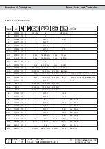
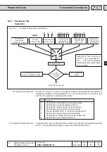
Functional Description
Protective Functions
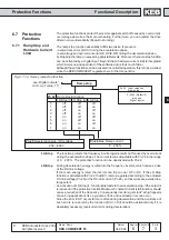
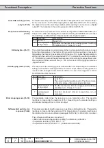
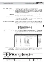
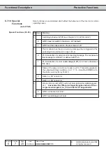
Response to E.EF (Pn.3)
With Pn.3 it is defined how the inverter reacts when an external error (E.EF; A.EF) is
triggered. Following reactions can be selected:
Pn.3 Response
0
Error; restart after Reset
1
Fast stop; modulation off;
restart after Reset
2
Fast stop; holding torque;
restart after Reset
3
Modulation off; automatic
restart
4
Fast stop; modulation off;
automatic restart
5
Fast stop; holding torque;
automatic restart
6
Protective function off; no
reaction
Description
Error message E.xx
Immediate switch off of modulation. Correct the error
for the restart and activate reset.
The prewarning changes to an error. The drive
remains in the error state until a reset signal is
recognized.
Status message A.xx
Fast stop - switch off of modulation after reaching
0Hz. Correct the error for the restart and activate
reset. The drive remains in condition fast stop until
a reset signal is recognized.
Status message A.xx
Fast stop - holding torque on reaching 0 Hz. Correct
the error for the restart and activate reset. The drive
remains in condition fast stop until a reset signal is
recognized.
Status message A.xx
Immediate switch off of modulation; the drive returns
automatically to normal operation, as soon as the
fault no longer exists.
Status message A.xx
Fast stop - switch off of modulation after reaching
0Hz. The drive returns automatically to normal
operation, as soon as the fault no longer exists.
Status message A.xx
Fast stop - Holding torque on reaching 0 Hz. The
drive returns automatically to normal operation, as
soon as the fault no longer exists.
no status message
No effect on the drive. Fault is being ignored.
Watchdog-time (Pn.6)
The Watchdog-time monitores communication on the external bus between operator
and e.g. PC. The response upon exceeding the adjusted time is defined with Pn.5.
The time is adjustable in the range of 0 (no reaction); 0.01...10.00 s.
The possible reactions correspond to the reactions of Pn.3 (see above). Depending
on the selected setting a status message E.buS or A.buS is output or fault is being
ignored.
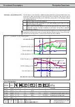
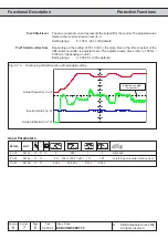
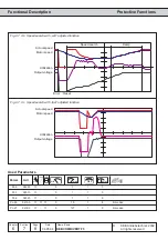
If the 100%-utilization of the inverter is exceeded by 5 %, the internal overload counter
starts to count forward. If the utilization falls below 100 %, the counter counts backward.
The current counter content can be read in parameter ru.39. Upon reaching 100 %
the inverter switches off with error message „E.OL“ and the counter counts backward.
When it has reached 0 % the status changes to E.nOL. The error can now be reset.
With Pn.9 a level between 0...100 % can be adjusted, at which the condition OL-
warning is fulfilled. The response to the warning signal is defined with Pn.8.
Response to E.buS (Pn.5)
Level OL-warning (Pn.9)