


6
10
9
KEB COMBIVERT F5
Name: Basis
17.02.03
6
Section
Page
Date
©
KEB Antriebstechnik, 2002
All rights reserved
Chapter
Functional Description
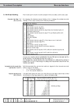
Encoder Interface
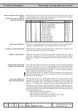
0° 90° 360°
A
A
B
B
N
N
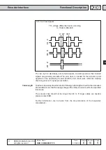
TTL-voltage differential levels according
to TIA/EIA-RS422-B
6.10.5.a Input signals
The two, by 90
∞
electrically out of phase signals, A and B as well as their inverted
signals are generally evaluated. The zero track is needed for the reference point
approach in the positioning module (F5-M/S). Zero track (also reference marking
channel) gives out 1 signal per revolution.
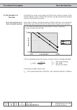
Cable length
To achieve an unobjectionable function following cable lengths should not be exceeded.
Precondition for it is that the supply voltage at the rotary encoder is within the specified
tolerances.
The encoder lines should not be longer than 50 m. If longer cables are needed,
please contact KEB.
Further information can be taken from the documentation of the respective
manufacturer.