


6
10
KEB COMBIVERT F5
14
Name: Basis
17.02.03
Chapter
Section
Page
Date
©
KEB Antriebstechnik, 2002
All rights reserved
Functional Description
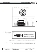
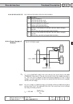
Encoder Interface
Formula:
actual position (ru.54) = position value - system offset (ec.33/34)
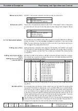
Which channel is taken for the actual value display is dependent on the adjusted
mode
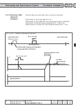
PS.0 = OFF /SYNCHRON -> CS.1
PS.0 = POSI ->PS.1
In case of posi at the output (cs.1 < > ps.1) it shall be driven speed controlled between.
In order to receive the actual position further on by ps.1, the posi mode can be left
only by disconnecting from input ps.2!
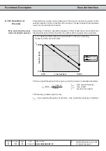
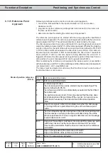
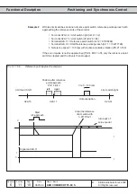
Start-up procedure of a multiturn encoder:
If a multiturn encoder is mounted in the unit, it displays any position after Power-
On (ec.29/30). By approaching to reference point and/or manual setting of the
reference point, the actual position in ru.54 can be defined now. For this the
system offset in parameters ec.33/34 is used. If the encoder leaves its value range
(final value), then its position value starts with ZERO
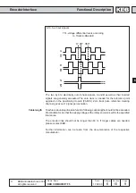
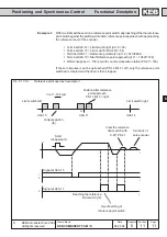
1.An overflow of the encoder may not lead to a jump in the actual position (ru.r4)
2.After power off >on the position value (ru.54) must be available.
Conclusion: the overflow of the encoder must be noticed.
For this the position in ec.31/ 32 is internally stored and compared with the position
of the encoder of ec.29/30 after power on. A recognized overflow is considered in
the system offset ec.33/34, i.e. the system offset is changed by the overflow.
After power off, the encoder may not change more than the half value range (final
value/2)!
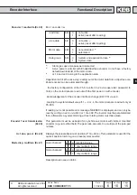
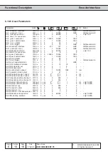
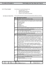
Ec.36 indicates the type of the first supported encoder interface.
0 no encoder detected
64 undefined type
The following hiperface types are supported:
2 SCS 60/70
7 SCM 60/70
34 SRS 50/60
39 SRM 50/60
Ec.37 indicates the status of intelligent encoder interfaces (Hiperface, ENDAT, etc.).
Ñ96ì is displayed if another encoder is used. With the F5-M/ S the change leads to the
display "E.Enc" and can be reset by a hardware reset. If "system position trimming
must take place" is displayed, either the motor data of the encoder must be read out
or a system position trimming must be done.
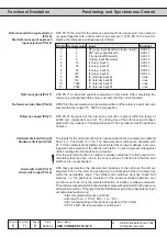
System offset Channel 1
(Ec.33)
System offset Channel 2
(Ec.34)
Encoder 1 Typ (Ec.36)
Encoder 1 state (Ec.37)