


6
10
KEB COMBIVERT F5
12
Name: Basis
17.02.03
Chapter
Section
Page
Date
©
KEB Antriebstechnik, 2002
All rights reserved
Functional Description
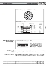
Encoder Interface
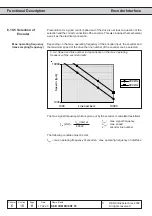
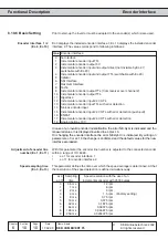
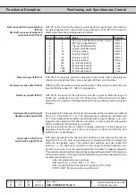
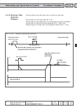
Pretend parameter ec.14 set dependently in the range from -2000...2000
Formula:
Ec.14 -2000...2000
ññññññññ = ñññññññññññññ
Ec.15 1000
An.53
=
motor poti
=
1
An.54
=
100Eh
=
ec.14
An.55
=
2000
=
100%
oP.53
100%
=
motor poti min. value
oP.52
set
0
100%
=
motor poti value
1
50%
2
50%
3
100%
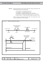
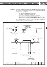
Example
Adjustments of the analog
parameter defaults
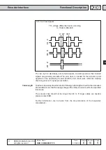
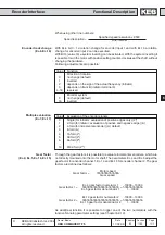
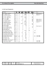
Simulation mode (Ec.27)
With this parameter an encoder simulation can be adjusted.
Bit
Value Function
0..1
Acceptance of the values
0
from channel 1
1
from channel 2
2
from current actual value
2..3
Number of increments to be output (at Bit 0..1 = 2)
0
256
4
512
8
1024
12
2048
4...5
Divisor
0
1 (direct)
16
2
32
4
Ec.27 adjusts the mode of the simulation channel. If channel 2 is adjusted with Ec.20
to incremental encoder output, then the mode in CH2 becomes effective with Ec.27
(Ec.27 source => CH2 useless). Otherwise the adjustments refer to a third pure
simulation channel (e.g. channel 2 15-poles).
When adjusting Ec.27 Bit 0...1 = actual value, then channel 2 may not be occupied,
since the internal encoder counter is used for the generation of the zero signal.