


6
7
KEB COMBIVERT F5
12
Name: Basis
04.05.04
Chapter
Section
Page
Date
©
KEB Antriebstechnik, 2002
All rights reserved
Functional Description
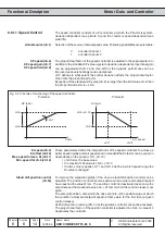
Protective Functions
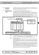
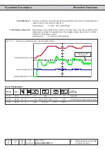
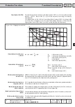
The interior temperature monitoring protects the inverter against malfunctions caused
by too high temperature in the interior of the inverter. Upon exceeding a unit-specific
temperature the interior fan is activated. If after approx. 10 minutes the temperature is
still too high, the switch off time adjusted with Pn.17 is started, the switching condition
„11“ OHI-warning is set and the adjusted response to the warning message is executed.
After expiration of the switch-off time (0...120 s) the error E.OHI is triggered (also see
„Digital Outputs“).
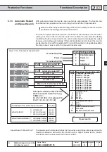
The response to the warning signal is defined with Pn.16. Depending on the selected
setting an error/status message E.OHI or A.OHI is ouput. After a cooling phase the
inverter status changes from E.OHI to E.nOHI or in case of warning from A.OHI to
A.nOHI and can then be reset.
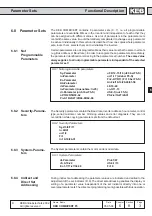
This parameter determines the response to a set selection error. The possible
reactions correspond to the reactions of Pn3. Depending on the selected setting an
error/status message E.Set or A.Set is output.
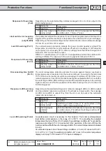
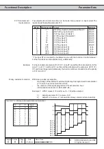
OHI stopping mode (Pn.16)
Pn.16 Response
0...5 as at Pn.3
6
warning signal only
at dig. output
7
warning signal
disabled
Description
as at Pn.3
The prewarning changes into an error. The drive remains
in the error status until a reset signal is detected.
No effect on the drive. Error is being ignored. Switching
condition do.0...7 Value „11“ is set.
Function disabled; interior temperature is not
evaluated.
E.Set stopping mode (Pn.18)
OHI delay time (Pn.17)
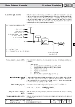
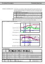
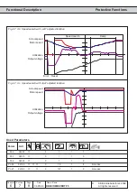
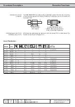
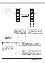
An electronic motor protective circuit-breaker is integrated in KEB COMBIVERT (see
Chapt. 6.7.8). When the tripping times, defined according to VDE 0660, are exceeded
the switching condition OH2-warning is set (also see „Digital outputs“).
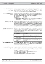
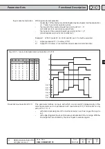
Response to OH2-warning
(Pn.14)
Pn.14 Response
0...5 see Pn.3
6
warning signal only
at dig. output
Description
see Pn.3
No effect on the drive. Error is being ignored. Switching
condition do.0...7 Value „10“ is set.
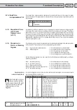
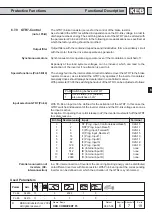
An electronic motor protective circuit-breaker is integrated in servo F5-S (see Chapt.
6.7.8). A level of 0...100 % of the tripping time is adjustable with Pn.15. On reaching
the adjusted level, the switching condition „OH2-warning“ is set (also see „Digital
outputs“). The response to the warning signal is defined with Pn.14.
Level OH2-warning (Pn.15)
(only for F5-S)
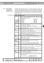
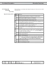
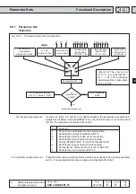
This parameter determines the response to a software limit switch error. The possible
reactions correspond to the reactions of Pn3. Depending on the selected setting and
the rotation direction an error/status message E.SLF/A.SLF or E.SLr/A.SLr is output.
Software limit switch error
response (Pn.66)
The soft ware switches are only active if:
• after a reference point approach or setting the reference point active
• the position is stored (PS.14 Bit 0-1 = 3)
• the position is valid (PS.14 Bit 7 = 1) (absolut value encoder)