


3
Hardware
Control Cards
3
1
5
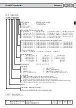
KEB COMBIVERT F5-M / S
Name: Basis
18.05.04
Section
Page
Date
©
KEB Antriebstechnik, 2002
All Rights reserved
Chapter
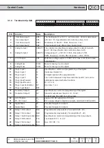
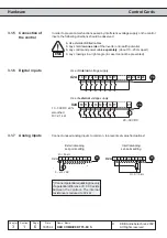
3.1.4
Terminal strip X2A
PIN
Function
Name
Description
1
+ Set Value input 1
AN1+
The input signal (0...±10 V; 0...±20 mA and 4...20 md is determined
2
- Set Value input 1
AN1-
with An.0 / 10. Specification and control see chap. 6.2.2.
3
+ Set Value input 2
AN2+
Resolution: 12 Bit, Ri = 30 k
Ω
, Scan time: 1 ms /
4
- Set Value input 2
AN2-
at fast setpoint input: 250 µs (see chapter 6.4.2)
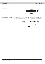
5
Analog Output 1
ANOUT1 The variable for outputting at analog output 2 is determined with
An.31 / 36. Specification and control see chap. 6.2.8.
6
Analog Output 2
ANOUT2 Voltage range: 0...±10V, Ri = 100
Ω ,
Resolution: 12 Bit
PWM frequency: 3,4 kHz, filter response 1. order: 178 Hz
7
+10 V Output
CRF
Reference voltage 10 VDC +5% / max. 4 mA for set value
potentiometer.
8
Analog Mass
COM
Mass for analog in- and outputs
9
Analog Mass
COM
Mass for analog in- and outputs
10
Progr. Input 1
I1
Specifications, control und programming of the digital
11
Progr. Input 2
I2
inputs see chapter 6.3
12
Progr. Input 3
I3
All digital inputs are free programmable.
13
Progr. Input 4
I4
The control release is firmly linked with the input ST, but can be
14
Progr. Input Forward
F
additional occupied with other functions.
15
Progr. Input Reverse
R
Ri = 2,1 k
Ω
16
Progr. Input Control Rel.
ST
Scan time: 1 ms
17
Progr. Input Reset
RST
18
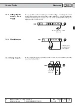
Transistor Output 1
O1
Specifications, control und programming of the digital
19
Transistor Output 2
O2
transistor outputs see chap. 6.3.12...6.3.22,
a total of max. 50 mADC for both outputs
20
+24 V Output
U
out
approx. 24V DC output (max.100 mA)
21
20...30 V Input
U
in
Ext. supply voltage for digital in-/outputs, potential 0V (X2A.22/23)
22
Digital Mass
0V
Potential for digital in-/outputs
23
Digital Mass
0V
Potential for digital in-/outputs
24
Relay 1 /NO contact
RLA
Programmable relay output 1 (Terminal X2A.24...26);
25
Relay 1 /NC contact
RLB
Programmable relay output 2 ( Terminal X2A.27...29)
26
Relay 1 /switching contact RLC
Specifications, control und programming of the relay outputs
27
Relay 2 /NO contact
FLA
see chapter 6.3.11...6.3.17
28
Relay 2 /NC contact
FLB
max. 30 V DC, 1 A
29
Relay 2 /switching contact FLC
1
2
3
4
5
6
7
8
9
10 11 12 13 14 15 16 17 18 19 20 21 22 23
24 25 26 27 28 29